Jharkhand Board JAC Class 10 Science Solutions Chapter 10 Light Reflection and Refraction Textbook Exercise Questions and Answers.
JAC Board Class 10 Science Solutions Chapter 10 Light Reflection and Refraction
Jharkhand Board Class 10 Science Light Reflection and Refraction Textbook Questions and Answers
Question 1.
Which one of the following materials cannot be used to make a lens?
(a) Water
(b) Glass
(c) Plastic
(d) Clay
Answer:
(d) Clay
[Hint: The material of a lens must be transparent but clay is opaque.]
Question 2.
The image formed by a concave mirror is observed to be virtual, erect and larger than the object. Where should be the position of the object?
(a) Between the principal focus and the centre of curvature
(b) At the centre of curvature
(c) Beyond the centre of curvature
(d) Between the pole of the mirror and its principal focus
Answer:
(d) Between the pole of the mirror and its principal focus.
Question 3.
Where should an object be placed in front of a convex lens to get a real image of the size of the object?
(a) At the principal focus of the lens
(b) At twice the focal length of the lens
(c) At infinity
(d) Between the optical centre of the lens and its principal focus
Answer:
(b) At twice the focal length of the lens
Question 4.
A spherical mirror and a thin spherical lens have each a focal length of – 15 cm. The mirror and the lens are likely to be …
(a) both concave.
(b) both convex.
(c) the mirror is concave and the lens is convex.
(d) the mirror is convex, but the lens is concave.
Answer:
(a) both concave.

Question 5.
No matter how far you stand from a mirror, your image appears erect. The mirror is likely to be _______.
(a) only plane.
(b) only concave.
(c) only convex.
(d) either plane or convex.
Answer:
(d) either plane or convex.
[Hint: Both give erect images. The size of image in plane mirror is same as the object but it is diminished in convex mirror.]
Question 6.
Which of the following lenses would you prefer to use while reading small letters found in a dictionary?
(a) A convex lens of focal length 50 cm
(b) A concave lens of focal length 50 cm
(c) A convex lens of focal length 5 cm
(d) A concave lens of focal length 5 cm
Answer:
(c) A convex lens of focal length 5 cm [Hint: Since a convex lens gives a magnified image of the object and the smaller the focal length, the more the magnifying power.]
Question 7.
We wish to obtain an erect image of an object, using a concave mirror of focal length 15cm. What should be the range of distance of the object from the mirror? What is the nature of the image? Is the image larger or smaller than the object? Draw a ray diagram to show the image formation in this case.
Solution:
When the object is placed between the pole and the principal focus of a concave mirror, an erect, virtual and enlarged image is formed. This image can be viewed in the mirror itself, not on the screen. In short, image is formed behind the mirror as shown in the figure 10.57.
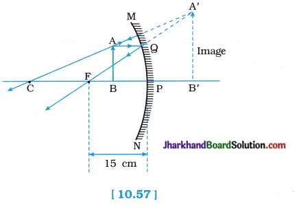
Therefore, the range of distance of the object from the mirror must be greater than zero and less than 15 cm (focal length of the concave mirror).
Question 8.
Name the type of mirror used in the following situations:
(a) Headlights of a car
(b) Side / rear-view mirror of a vehicle
(c) Solar furnace
Support your answer with reason.
Answer:
(a) For headlights of a car, a concave mirror is used.
The light source is kept at the focus s of the mirror. On reflection, a strong? parallel beam of light emerges out.
(b) For side / rear-view mirror of a vehicle, s convex mirror is used.
This is because its field of view is very large and it forms a virtual, erect and diminished image of the object behind the vehicle, which enables a driver to see most of the traffic behind him/her.
(c) For a solar furnace, a concave mirror is used.
Light from the Sun, on reflection from t the mirror, is concentrated at the focus of s the mirror, producing heat and temperature increases sharply up to 180°C-200°C
Question 9.
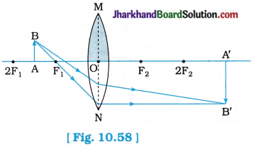
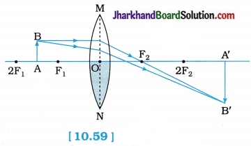
One-half of a convex lens is covered with a black paper. Will this lens produce a complete image of the object? Verify your answer experimentally. Explain your observations.
Answer:
Yes.
Even when one-half of a convex lens is covered with a black paper, the lens produces a complete (or full) image of the object.
Here, the intensity (brightness) of image will become one-forth as that with complete lens exposed, because less number of light rays can be passed / refracted through the lens.
The nature, size and location of the image will be the same since light from all parts of the object reach the exposed part of the lens.
It can be understood by the following two cases (Experimental verification) :
(1) When the upper half of the lens is covered :
In this case, the ray of light coming from the object will be refracted by the lower half of the lens.
These rays meet at the other side of the lens to form the image of the given object.
(2) When the lower half of the lens is covered:
In this case, the ray of light coming from the object will be refracted by the upper half of the lens.
These rays meet at the other side of the lens to form the image of the given object.
[Note: Covering one-half of the lens reduces the brightness of the image.]
Question 10.
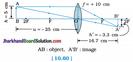
An object 5 cm in length is held 25 cm away from a converging lens of focal length 10 cm. Draw the ray diagram and find the position, size and the nature of the image formed.
Solution:
Here, Object size h = + 5 cm
Object distance u = – 25 cm
Focal length of lens f = + 10 cm
(∵ Converging, i.e., Convex lens)
Image distance v = ?
Image height h’ = ?
As, \(\frac { 1 }{ f }\) = \(\frac { 1 }{ v }\) – \(\frac { 1 }{ u }\)
\(\frac { 1 }{ v }\) = \(\frac { 1 }{ f }\) + \(\frac { 1 }{ u }\)
= \(\frac{1}{(+10)}+\frac{1}{(-25)}=\frac{5-2}{50}=\frac{3}{50}\)
= 16.67 cm
Image distance v is positive. This shows that the image formed is real and on the other side of the lens, at 16.67 cm from the lens as shown in the figure 10.60:
Now, Magnification m = \(\frac { h’ }{ h }\) = \(\frac { v }{ u }\)
∴ h’ = h\(\frac { v }{ u }\)
= \(\frac { 1 }{ f }\)
= – \(\frac { 10 }{ 3 }\) cm
= – 3.3 cm
The negative (minus) sign shows that the image is inverted, real, diminished (3.3 cm).
Figure 10.60 show the position, size and nature of the image formed.
[Note: The ray diagram can be drawn without calculating v and h’. Once, f, u and h are fixed, v and h’ have definite values.

Question 11.
A concave lens of focal length 15 cm forms an image at 10 cm from the lens. How far is the object placed from the lens? Draw the ray diagram.
Solution:
Here, Focal length of the lens f = – 15cm (∵ Concave lens)
Image distance v = – 10 cm
(∵ In case of a concave lens the image is formed on the same side of the object)
Object distance u = ?
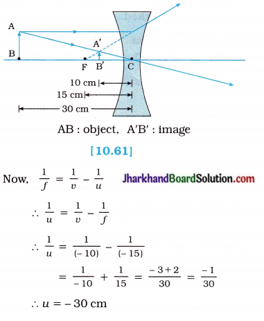
The negative (minus) sign shows that the object is placed on the left side of the lens.
Question 12.
An object is placed at a distance of 10 cm from a convex mirror of focal length 15 cm. Find the position and nature of the image.
Solution:
Here, Object distance u = – 10 cm
Here, Object distance u = – 10 cm
Focal length of the mirror f = + 15 cm (∵ Convex mirror)
Image distance v = ?
Using the mirror formula \(\frac { 1 }{ f }\) = \(\frac { 1 }{ u }\) + \(\frac { 1 }{ v }\)
We have
\(\frac { 1 }{ v }\) = \(\frac { 1 }{ f }\) – \(\frac { 1 }{ u }\)
= \(\frac{1}{(+15)}-\frac{1}{(-10)}\)
= \(\frac{1}{15}+\frac{1}{10}\)
= \(\frac { 2+3 }{ 3 }\)
= \(\frac { 5 }{ 30 }\)
= \(\frac { 1 }{ 6 }\)
∴ v = 6 cm
The positive (plus) sign of v indicates that the image is formed behind the mirror.
Now, magnification m = – \(\frac { v }{ u }\) = – \(\frac { 6 }{ – 10 }\) = + 0.6
Positive value of magnification indicates that the image is virtual and erect.
The magnitude of magnification is 0.6, which is less than 1. This shows that the S image is diminished.
Question 13.
The magnification produced by a plane mirror is + 1. What does this mean?
Solution:
Here, m = + 1
As, m = \(\frac { h’ }{ h }\)
\(\frac { h’ }{ h }\) = + 1
∴ h’ = h
So, the size of the image is equal to the size of object.
Further, the positive (plus) sign of m indicates that the image is erect and hence virtual.
Again, m = – \(\frac { v }{ u }\) and m = + 1
∴ – \(\frac { v }{ u }\) = 1
∴ v = – u
This shows that the image is formed behind the mirror and the distance of the image from the mirror equals that of the object from the mirror.
Question 14.
An object 5.0 cm in length is placed at a distance of 20 cm in front of a convex mirror of radius of curvature 30 cm. Find the position of the image, its nature and size.
Solution:
Here, Size of object h = + 5.0 cm
Object distance u = – 20 cm
Radius of curvature R = + 30 cm (∵ Convex mirror)
Focal length f = \(\frac { + 30 cm }{ 2 }\) = + 15 cm
Image distance v = ?
Image size h’ = ?
Mirror formula: \(\frac { 1 }{ v }\) + \(\frac { 1 }{ u }\) = \(\frac { 1 }{ f }\)
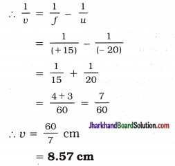
The positive (plus) sign of u indicates that the image is behind the mirror or on the right-hand side of the mirror.
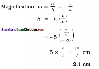
Positive value of image height indicated that the image is virtual and erect.
Moreover, h’ < h
So, the image is smaller in size than the object.
Question 15.
An object of size 7.0 cm is placed at 27 cm in front of a concave mirror of focal length 18 cm. At what distance from the mirror should a screen be placed, so that a sharp focussed image can be obtained? Find the size and the nature of the image.
Solution:
Here, Object size h = 7.0 cm
Object distance u = – 27 cm
Focal length f = – 18 cm
(∵ Concave mirror)
Image distance u = ?
Image size h’ = ?
From mirror formula :
\(\frac { 1 }{ v }\) + \(\frac { 1 }{ u }\) = \(\frac { 1 }{ f }\)
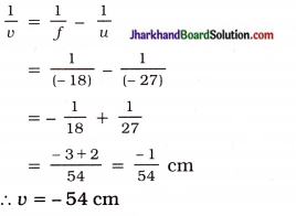
The negative (minus) sign of v indicates that ’ the image is formed on the same side of the object. So, screen should be held in front of the mirror at a distance of 54 cm from the mirror. The image can be obtained on the screen and hence, it is real.
Now, magnification m = \(\frac { h’ }{ h }\) = – \(\frac { v }{ u }\)
∴ h’ = – h(\(\frac { v }{ u }\))
= – 7.0 (\(\frac { -54 }{ -27 }\))
= – 14 cm
The negative (minus) sign of h’ shows that the image is inverted and hence would be real.
Question 16.
Find the focal length of a lens of power -2.0D. What type of lens is this?
Solution :
Here, Focal length of the lens f = ?
Power P = – 2.0 D = – 2.0 m-1
Now,
As, P = \(\frac { 1 }{ f }\)
f = \(\frac { 1 }{ p }\)
= \(\frac { 1 }{ -2D }\)
= – 0.5 cm
As the power of the lens is negative (given), the lens must be concave.
Question 17.
A doctor has prescribed a corrective lens of power + 1.5 D. Find the focal length of the lens. Is the prescribed lens diverging or converging?
Solution:
Here, Power P = + 1.5 D = + 1.5 m-1
Focal length f = ?
From, f = \(\frac { 1 }{ p }\)
f = \(\frac { 1 }{ 1.5 D }\)
= 0.67 m
= 67 cm
As the power of the lens is positive (given), it is a converging lens, i.e., a convex lens.
Jharkhand Board Class 10 Science Light Reflection and Refraction InText Questions and Answers
Question 1.
Define the principal focus of a concave mirror.
Answer:
The point on the principal axis of a concave mirror, at which rays of light incident on the mirror in a direction parallel to the principal axis (actually) meet / intersect after reflection from the mirror is called the principal focus (F) of the concave mirror.
[Note : In general, the point on the principal axis where rays of light incident parallel to the principal axis converge to or appear to diverge from after reflection is called the principal focus of the spherical mirror.]
Question 2.
The radius of curvature of a spherical mirror is 20 cm. What is its focal length?
Solution:
Here, R = 20 cm; f =?
As f = \(\frac { R }{ 2 }\), f = \(\frac { 20 }{ 2 }\)
= 10 cm
[Note: According to the New Cartesian sign convention, if the given spherical mirror is a convex mirror, then f = + 10cm and if the given spherical mirror is a concave mirror, then f = – 10 cm.]
Question 3.
Name a mirror that can give (form) an erect and enlarged image of an object.
Answer:
Concave mirror:
A concave mirror produces an erect and enlarged image of an object, when an object is placed between the pole and principal focus of the concave mirror.
Question 4.
Why do we prefer a convex mirror as a rear-view mirror in vehicles?
Answer:
This is because a convex mirror (always) forms an erect, virtual and diminished image of an object, wherever the object may be located.
Also, a convex mirror has a wider field of view, relative to a plane mirror, as it is curved outwards. Thus, a convex mirror fitted on the side of a vehicle enables the driver to view much larger area than that would be possible with a plane mirror, enabling the driver to see traffic behind him/her to facilitate safe driving.

Question 5.
Find the focal length of a convex mirror whose radius of curvature is 32 cm.
Solution:
Here, the radius of curvature R = 32 cm
We know that, the focal length f = \(\frac { R }{ 2 }\)
∴ f = \(\frac { 32 }{ 2 }\) = 16 cm
Question 6.
A cancave mirror produces three times magnified (enlarged) real image of an object placed at 10 cm in front of it. Where 5 is the image located?
Solution:
Here, the linear magnification m = – 3
(negative sign for a real image, which is inverted)
The object distance u = – 10 cm
(object distance (real) is always negative)
The image distance v =?
As m = – \(\frac { v }{ u }\)
v = – mu
∴ v = – (-3) (- 10)
= – 30 cm
Thus, the real image is located at 30 cm in front of the mirror (on the same side as the object).
Question 7.
A ray of light travelling in air enters obliquely into water. Does the light ray bend towards the normal or away from the normal? Why?
Answer:
For oblique incidence, the light ray bends towards the normal, on entering water. It happens because water is optically denser than air.
The speed of light is higher in an optically rarer medium than in an optically denser medium. So, a ray of light travelling from air to water slows down and bends towards the normal.
OR

Thus, the angle of refraction is less than the angle of incidence. It implies that the light ray bends towards the normal.
Question 8.
Light enters from air to glass having refractive index 1.50. What is the speed of light in the glass? The speed of light in vacuum is 3 x 10⁸ m s-1.
Solution:
Speed of light in vaccum c = 3 x 10⁸ m s-1.
Refractive index of glass ng = 1.50
Speed of light in glass v = ?
Now, absolute refractive index of glass,
ng = \(\frac { c }{ v }\)
∴ The speed of light in the glass,
v = \(\frac{c}{n_{\mathrm{g}}}=\frac{3 \times 10^8}{1.50}\)
= 2 x 10⁸ m s-1.
Question 9.
Find out from Table 2 (Given with Q. 42), the medium having highest optical density. Also, find the medium with lowest optical density.
Answer:
The higher the refractive index, the higher is the optical density. Diamond has the highest optical density as it has the highest refractive index, 2.42 and air has the lowest optical density as it has the lowest refractive index, 1.0003.
Question 10.
You are given kerosene, turpentine and water. In which of these does the light travel fastest? Use the information given in Table 2.
Answer:
From Table 2,
refractive index of kerosene = 1.44
refractive index of turpentine = 1.47 and
refractive index of water = 1.33
Here, from given liquids, turpentine has the highest refractive index and water has the lowest refractive index.
Now, the lower the refractive index of a medium, the higher is the speed of light in the medium.
Hence, out of the given liquids the light travels fastest in water.
Question 11.
The refractive index of diamond is 2.42. What is the meaning of this statement?
Answer:
Refractive index of diamond
= \(\frac{\text { Speed of light in vacuum / air }}{\text { Speed of light in diamond }}\)
∴ Speed of light in diamond
= \(\frac{\text { Speed of light in vacuum / air }}{\text { Refractive index of diamond }}\)
This expression states that the speed of light in diamond is \(\frac { 1 }{ 2.42 }\) times the speed of light in vacuum / air.
Speed of light in diamond = \(\frac{3 \times 10^8}{2.42}\)
= 1.24 x 10⁸ms-1
In other words, it can also be said that, the ratio of the speed of light in vacuum/air to the speed of light in diamond is equal to 2.42.
Question 12.
Define 1 dioptre of power of a lens.
OR
Define the dioptre.
Answer:
1 dioptre is the power of a lens of focal length 1 metre.
Question 13.
A convex lens forms a real and inverted image of a needle at a distance of 50 cm from it. Where is the needle placed in front of the convex lens if the image is equal to the size of the object? Also, find the power of the lens.
Solution:
A convex lens forms a real, inverted image of the same size as that of the object, if the object is placed at 2F1.
In this case v = + 50 cm and m = – 1
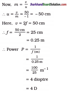
Thus, the needle is placed at 50 cm from the convex lens of power 4 D.
Question 14.
Find the power of a concave lens of focal length 2 m.
Solution :
Here, focal length f = – 2 m (∵ Concave lens)
∴ Power P = \(\frac { 1 }{ f(m) }\)
= \(\frac { 1 }{ -2m }\)
= – 0.5 m-1
= – 0.5 dioptre
= – 0.5 D
Activity 10.1 [T. B. Pg. 161]
To determine the nature of the inner and outer curved surface of a spoon.
Procedure :
1. Take a large shining spoon. Try to view your face in its inner curved surface.
- Do you get the image?
- Is it smaller or larger?
2. Move the spoon slowly away from your face. Observe the image.
3. Reverse the spoon and repeat the activity.
- How does the image look like now?
4. Compare the characteristics of the image on the two surfaces.
Observation :
- Yes.
- The image formed is enlarged and erect when the spoon is closer to the face.
- As the spoon is moved slowly away from the face, the image becomes large and inverted. When the face is very far off, highly diminished and inverted image of our face is seen.
- When the spoon is reversed, the image formed by the outer surface of the spoon is virtual and diminished in size.
- Now, if we move the spoon away from our face, the image moves away, however the image continues to be virtual and diminished in size.
- Finally, at last the image is diminished to almost point-size.
Conclusion:
The inner surface of the spoon acts as a concave mirror, whereas the outer surface acts as a convex mirror.

Activity 10.2 [T. B. Pg. 162]
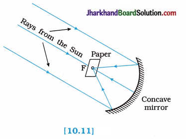
To show the converging nature of a concave mirror and find its focal length.
Procedure:
- Hold a concave mirror in your hand and direct its reflecting surface towards the Sun.
- Direct the light reflected by the mirror on to a sheet of paper held close to the mirror.
- Move the sheet of paper back and forth gradually until you find on the paper sheet a bright, sharp spot of light.
- Hold the mirror and the paper in the same position for a few minutes.
- What do you observe? Why?
Observation:
The paper initially turns blackish, then burns producing smoke. Eventually it catches fire. The light from the Sun is converged at a point, as a sharp bright spot by the mirror. In fact, this spot of light is the image of the Sun on the sheet of paper.
This point is the principal focus of the concave mirror. The heat produced due to concentration of sunlight ignites the paper.
Conclusion:
- The distance of this image of the Sun from the pole of the mirror gives the approximate value of the focal length of the concave mirror.
- It is also concluded that when a parallel beam of light from a far off object falls on a concave mirror, a real, inverted and point-ized image is formed at the focus of the concave mirror.
Activity 10.3 [T. B. Pg. 163]
To locate the image formed by a concave mirror for different positions of the object.
Procedure :
1. Take a concave mirror.
2. Find out its approximate focal length in the way described in Activity 10.2.
3. Note down the value of the focal length.
4. Mark a straight line on a table with a chalk. Place the concave mirror on a stand. Place the stand over the line such that the pole of the mirror lies over the line.
5. Draw with a chalk two more straight lines parallel to the previous line such that the distance between any two successive lines is equal to the focal length of the mirror.
These lines will now correspond to the positions of the points P F and C respectively.
(Remember : For a spherical mirror of small aperture, the principal focus F lies mid-way between the pole P and centre of curvature C.)
6. Keep a bright object, say a burning candle, at a position far beyond C.
Place a paper screen and move it in front of the mirror till you obtain a sharp bright image of the candle flame on it.
7. Observe the image carefully. Note down its nature, position and relative size with respect to the object size.
8. Repeat the activity by placing the candle –
- just beyond C
- at C
- between F and C
- at F
- between P and F
In one of the cases, you may not get the image on the screen. Identify the position of the object in such a case. Where would you look to observe the image of that object?
9. Note down and tabulate your observations.
Observation:
1. Image formation by a concave mirror for different positions of the object.
| Position of the object | Position of the image | Size of the image | Nature of the image |
| At infinity | At the focus F | Highly diminished, point-sized | Real and inverted |
| Just beyond C | Between F and C | Diminished | Real and inverted |
| At C | At C | Same size | Real and inverted |
| Between C and F | Beyond C | Enlarged | Real and inverted |
| At F | At infinity | Highly enlarged | Real and inverted |
| Between P and F | Behind the mirror | Enlarged | Virtual and erect |
2. When an object (the burning candle in the present case) is placed between P and F, its image cannot be obtained on the screen.
3. Hence, to observe its image, in this case one has to look in the mirror itself because the image is virtual.
Conclusion:
The nature, position and size of the image formed by a concave mirror depends on the position of the object in relation to the points E F and C.
Activity 10.4 [T. B. Pg. 166]
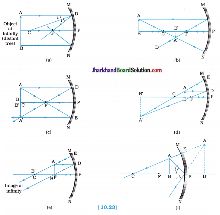
To locate the image formed by a concave mirror for different positions of an object using ray diagrams.
Procedure:
- Draw a neat ray diagram for each position of the object as discussed in the Activity 10.3. You may take any two of the rays (mentioned in the previous point 10.2.2), for locating the image.
- Observe the nature, position and relative size of the image formed in each case.
- Tabulate the results in a convenient format.
Observation:
The following figures illustrate the ray diagrams for the formation of image by a concave mirror for various positions of the object:
Conclusion:
Image formation by the concave mirror for different positions of an object using ray diagrams is tabulated as follows :
| Position of the object | Position of the image | Size of the image | Nature of the image |
| At infinity | At the focus F | Highly diminished, point-sized | Real and inverted |
| Just beyond C | Between F and C | Diminished | Real and inverted |
| At C | At C | Same size | Real and inverted |
| Between C and F | Beyond C | Enlarged | Real and inverted |
| At F | At infinity | Highly enlarged | Real and inverted |
| Between P and F | Behind the mirror | Enlarged | Virtual and erect |
Activity 10.5 [T. B. Pg. 167]
To locate the image formed by a convex mirror for different positions of an object.
Procedure:
- Take a convex mirror. Hold it in one hand.
- Hold a pencil in the upright position in the other hand.
- Observe the image of the pencil in the mirror.
- Is the image erect or inverted? Is it diminished or enlarged?
- Move the pencil away from the mirror slowly.
- Does the image become smaller or larger?
- Repeat this activity carefully.
- State whether the image will move closer to or farther away from the focus as the object is moved away from the mirror.
Observation:
1. When we hold a pencil in the upright position in front of a convex mirror, the image of the pencil is observed on the back side of the mirror, i.e., in the mirror itself.
The image is erect and virtual.
The image is diminished in size relative to the object.
2. When the pencil is moved away from the mirror slowly, the image becomes smaller and smaller, moving away from the mirror.
3. On repeating this activity, we find that as the object is moved away from the mirror, the image moves closer to the focus of the mirror.
Conclusion:
This activity confirms all the characteristics of the images formed by a convex mirror for different positions of the object and it is tabulated as follows :
| Position of the object | Position of the image | Size of the image | Nature of the image |
| At infinity | At the focus F, behind the mirror | Highly diminished, point-sized | Virtual and erect |
| Between infinity and the pole P of the mirror | Between P and F, behind the mirror | Diminished | Virtual and erect |
Activity 10.6 [T. B. Pg. 167]
To demonstrate the wide field of view nature of a convex mirror.
Procedure:
- Observe the image of a distant object, say a distant tree in a plane mirror.
- Could you see a full-length image?
- Try with plane mirrors of different sizes.
- Did you see the entire object in the image?
- Repeat this activity with a concave mirror.
- Did the concave mirror show full-length image of the object?
- Now, try using a convex mirror.
- Did you succeed?
- Explain your observation with reason.
Observation :
No, we can not see the full-length image of an object in plane mirror.
When we try with plane mirrors of different sizes, we find that the entire object in the image is seen when the size of the plane mirror is at least half of the size of the object.
No, concave mirror did not show full-length S image of the object (here a distant tree).
When we use a small convex mirror, we succeed in seeing the full-length image of an object, wherever the object may be located.

The reasons for these observations are as follows :
(1) In a plane mirror, size of image is S always equal to the size of the object.
(2) In case of a concave mirror, when object is between P and F, then only its enlarged, virtual and erect image is seen behind the concave mirror.
(i.e., full-length image of an object can be seen).
But here our object is far away from the concave mirror, e.g., distant tree; so its full- length image can not be seen in the concave mirror itself (i.e., behind the concave mirror).
(3) While, in a convex mirror, the image is always virtual, erect and smaller than the object, wherever the object may be located.
Conclusion:
Out of plane mirror, concave mirror and convex mirror, only a convex mirror can show a full-length image of a tall object in all its positions.
OR
A convex mirror has a wide field of view and the image formed by it is always virtual, erect and shorter than the object, wherever the object may be located.
Activity 10.7 [T. B. Pg. 172]
To demonstrate refraction of light.
OR
To show that the apparent depth of the bucket filled with water is less than the real depth of the bucket.
Procedure:
- Place a coin at the bottom of a bucket filled with water.
- With your eye to a side above water, try to pick up the coin in one go.
- Did you succeed in picking up the coin?
- Repeat the Activity.
- Why did you not succeed in doing it in one go?
- Ask your friends to do this.
- Compare your experience with theirs.
Observation:
No.
When you try picking up the coin with your eye to a side above water, you do not succeed in one go.
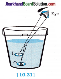
The reason for this can be explained as follows :
As shown in the figure 10.31, a coin is at point ‘O’ at the bottom of a bucket filled with water.
When we view this coin with our eye to a side above water, we observe the image I of the coin, which is above ‘O’. When we try to pick up this coin in one go, we do not succeed in picking up the coin. This is because we move our hand up to I, where the coin is being observed, but actually the coin lies below at O, the bottom of the bucket.
When our friends try the same way, they also fail to pick up the coin.
Conclusion:
In going from water to air, rays of light bend away from the normal and the bottom of the bucket appears to be raised, i.e., the apparent depth of the bucket is less than the real depth of the bucket.
Activity 10.8 [T. B. Pg. 172]
To show that the object in water appears to be raised due to refraction.
OR
Apparent depth of an object in the large shallow bowl filled with water increases as its real depth increases.
Procedure:
- Place a large shallow bowl filled with water on a table and put a coin in it.
- Move away slowly from the bowl. Stop when the coin just disappears from your sight.
- Ask a friend to pour water gently into the bowl without disturbing the coin.
- Keep looking for the coin from your position.
- Does the coin becomes visible again from your position?
- How could this happen?
Observation:
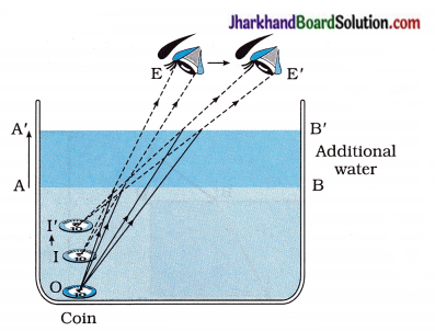
O = Real position of the coin
I = Initial apparent position of the coin
I’ = New apparent position of the coin
As shown in the figure 10.32, in a large shallow bowl filled with water, the real position of the coin is ‘O’.
On account of refraction of light the coin appears raised from O to I. Image I of the coin appears to be raised which is original apparent position of a coin.
When we move our eye slowly away from the bowl as shown by an arrow in the figure, the coin disappears from our sight. This happens because rays starting from the coin O fail to enter our eye, after refraction at water surface AB.
When a friend pours water gently into the bowl without disturbing the coin, the coin becomes visible again as it appears raised further to position I’.
This happens because on adding water, the real- depth of the coin increases. As the apparent depth of a coin is equal to the real depth divided by the refractive index (n) of water, the apparent depth of the coin also increases. Hence, the coin appears raised from I to I’. Therefore, the coin becomes visible from the displaced position (new position) of our eye.
Conclusion:
The coin becomes visible again and slightly raised above its actual position on pouring water into the bowl. This is because of refraction of light.
In other words, apparent depth of a coin in the large shallow bowl filled with water increases as its real depth increases.
Activity 10.9 [T. B. Pg. 172]
To show that refraction does not occur for normal incidence.
Procedure:
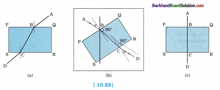
1. Draw a thick straight line in ink, over a sheet of white paper placed on a table.
2. Place a glass slab over the line in such a way that one of its edges makes an angle with the line.
3. Look at the portion of the line under the slab from the sides.
- What do you observe?
- Does the line under the glass slab appear to be bent at the edges?
4. Next, place the glass slab such that it is normal to the line.
- What do you observe now?
- Does the part of the line under the glass slab appear bent?
5. Look at the line from the top of the glass slab.
- Does the part of the line, beneath the slab, appear to be raised?
- Why does this happen?
Observation :
- When we look at the portion of the line under the slab from sides, careful observation shows that line AB is bent at edge B and line BC at edge C. [figure 10.33 (a)]
- Yes. The line under the glass slab appears bent at edges B and C.
- On placing the glass slab normal to the line, we observe that the part of the line under the glass slab does not appear bent, [figure 10.33 (c)]
- No. The line under the glass slab does not appear bent at edges B and C.
- Yes. The part of the line, beneath the slab, appears raised while looking at the line from the top of the glass slab.
- This is due to refraction of light.
Conclusion:
The object appears raised due to refraction of light and for normal incidence, refraction of light does not occur.
Activity 10.10 [T. B. Pg. 173]
To show the refraction of light and lateral displacement through a rectangular glass slab.
Procedure:
- Fix a sheet of white paper on a drawing board using drawing pins.
- Place a rectangular glass slab over the sheet in the middle.
- Draw the outline of the slab with a pencil and name the outline as ABCD.
- Take four identical pins.
- Fix two pins, say E and F, vertically such that the line joining the pins is inclined to the edge AB.
- Look for the images of the pins E and F through the opposite edge.
- Fix two other pins, say G and H, such that these pins and the images of E and F lie on a straight-line.
- Remove the pins and the slab.
- Join the positions of tip of the pins E and F and produce the line up to AB. Let EF meet AB at O. Similarly,
- join the positions of tip of the pins G and H and produce it up to the edge CD. Let HG meet CD at O’.
- Join O and O’. Also, produce EF up to P as shown by a dotted line in the following figure.
- At O, draw NN’ perpendicular to AB. At O’, draw MM’ perpendicular to CD. Also, draw O’L perpendicular to OP.
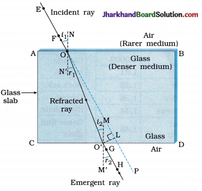
[Note : (1) In figure 10.34, face AB is air-glass interface and face CD is glass-air interface. ( 2 ) Reflection of light is not shown in the figure.]
Observation :
- At O, light ray along EF enters from air into glass. It bends towards the normal NN’. This is the first refraction.
- At O’, the light ray enters from glass into air. It bends away from the normal MM’ and travels 5 along GH. This is second refraction.
- Here, angle of emergence r2 is equal to angle of incidence i1, i.e., the emergent ray is parallel to the original direction of the incident ray. This is because there is identical medium, air in this case, adjacent to both edges AB and CD.
- However, the light ray is shifted sideways slightly. This is lateral displacement and is represented by O’L.
Conclusion:
- The ray of light travelling from a rarer medium (air in this case) to a denser medium (glass in this case) bends towards the normal.
- The ray of light travelling from a denser medium (glass in this case) to a rarer medium (air in this case) bends away from the normal.
- The emergent ray is parallel to the incident ray but is slightly displaced sideways.
Activity 10.11 [T. B. Pg. 177]
To show the converging nature of a convex? lens and find its focal length.
Procedure :
1. Hold a convex lens in your hand. Direct it towards the Sun.
2. Focus the light from the Sun (through lens) on a sheet of paper. Obtain a sharp bright image? of the Sun.
3. Hold the paper and the lens in the same position for a while.
Keep observing the paper.
- What happened?
- Why?
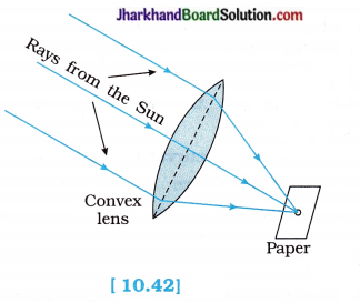
Observation :
- When the paper and the lens were held in the same position for sometime, the paper began to burn producing smoke. After sometime, it caught fire.
- Because, the light from the Sun constitutes parallel rays of light. These rays were converged by the lens at the sharp bright spot formed on the paper and so heat is produced by these Sun rays as they concentrate on the spot. This caused the paper to burn.
Conclusion:
- When a parallel beam of light from a far-off object like the Sun falls on a convex lens, a real, inverted, point size image of the Sun is formed at the focus of the lens.
- The distance between the position of the lens and the position of the image of the Sun gives the approximate focal length of the lens.
[Note : The distance between the lens and the image of the Sun on the paper is the approximate focal length of the lens.]
Activity 10.12 [T. B. Pg. 178]
To locate the position and examine the nature of the image formed by a convex lens for different positions of the object.
Procedure:
- Take a convex lens. Find its approximate focal length in a way described in Activity 10.11.
- Draw five parallel lines, using chalk, on a long table such that the distance between the successive lines is equal to the focal length of the lens.
- Place the lens on a lens stand. Place it on the central line such that the optical centre of the lens lies just over the line.
- The two lines on either side of the lens correspond to F and 2F of the lens respectively. Mark them with appropriate letters such as 2F1, F1, F2 and 2F2 respectively.
- Place a burnig candle, far beyond 2F1 to the left. Obtain a clear sharp image on a screen on the opposite side of the lens.
- Note down the nature, position and relative size of the image.
- Repeat this Activity by placing the object just beyond 2F1, at 2F1, between F1 and 2F1, at F1, between F1 and O.
- Note down and tabulate your observations.
Observation:
Position, relative size and the nature of the image formed by a convex lens for various positions of the object.
| Position of the object | Position of the image | Relative size of the image | Nature of the image |
| At infinity | At focus F2 | Highly diminished, point-sized | Real and inverted |
| Beyond 2F1 | Between F2and 2 F2 | Diminished | Real and inverted |
| At F1 | At 2F2 | Same size | Real and inverted |
| Between F1and 2F1 | Beyond 2 F2 | Enlarged | Real and inverted |
| At focus F1 | At infinity | Infinitely large or Highly enlarged | Real and inverted |
| Between focus F1 and optical centre O* | On the same side of the lens as the object | Enlarged | Virtual and erect |
Conclusion:
The nature, position and relative size of the image formed by a convex lens for various positions of the object depends on the position of the object in front of the lens.
Activity 10.13 [T. B. Pg. 179]
To locate the position and examine the nature of the image formed by a concave lens for different positions of the object.
Procedure:
- Take a concave lens. Place it on a lens stand.
- Place a burning candle on one side of the lens.
- Look through the lens from the other side and observe the image. Try to get the image on a screen, if possible.
- If not, observe the image directly through the lens.
- Note down the nature, relative size and approximate position of the the image.
- Move the candle away from the lens. Note the change in the size of the image.
- What happens to the size of the image when the candle is placed too far away from the lens?
- What conclusion can you draw from this Activity?
Observation:
The image formed by a concave lens, when a burning candle is kept too far away from the lens is highly diminished, i.e., point-sized.
Position, relative size and the nature of the image formed by a concave lens for various position of an object
| Position of the object | Position of the image | Relative size of the image | Nature of the image |
| At infinity | At focus F1 | Highly diminished, point-sized | Virtual and erect |
| Between infinity and optical centre O of the lens | Between focus F1 and optical centre O | Diminished | Virtual and erect |
Conclusion:
The image formed by a concave lens is always virtual, erect and diminished irrespective of the position of the object.
![]()
![]()
![]()






 fins cut out of a metal sheet into these slits.