Jharkhand Board JAC Class 10 Science Solutions Chapter 12 Electricity Textbook Exercise Questions and Answers.
JAC Board Class 10 Science Solutions Chapter 12 Electricity
Jharkhand Board Class 10 Science Electricity Textbook Questions and Answers
Question 1.
A piece of wire of resistance R is cut into five equal parts. These parts are then connected in parallel. If the equivalent resistance of this combination is R’, then the ratio \(\frac { R }{ R }\) is
(a) \(\frac { 1 }{ 25 }\)
(b) \(\frac { 1 }{ 5 }\)
(c) 5
(d) 25
Answer:
(d) 25
Hint Here, the resistance of a piece of wire is R. This piece of wire is cut into five equal parts, so the resistance of each part would be \(\frac { R }{ 5 }\).
Now, these five parts each having resistance of \(\frac { R }{ 5 }\) are connected in parallel.
The equivalent resistance R’ of this combination is given by
\(\frac{1}{R^{\prime}}=\frac{1}{\left(\frac{R}{5}\right)}+\frac{1}{\left(\frac{R}{5}\right)}+\frac{1}{\left(\frac{R}{5}\right)}+\frac{1}{\left(\frac{R}{5}\right)}+\frac{1}{\left(\frac{R}{5}\right)}\)
∴ \(\frac{1}{R^{\prime}}=\frac{5}{R}+\frac{5}{R}+\frac{5}{R}+\frac{5}{R}+\frac{5}{R}=\frac{25}{R}\)
∴ \(\frac { R }{ R’ }\) = 25
Question 2.
Which of the following terms does not represent electrical power in a circuit?
(a) I²R
(b) IR²
(c) VI
(d) \(\frac{V^2}{R}\)
Answer:
(b) IR²
Hint: Electric power P = VI = (IR) I = I²R
Thus, the three expressions given in (a), (c) and (d) represent power while expression given in (b) does not.
![]()
Question 3.
An electric bulb is rated 220 V and 100 W. When it is operated on 110 V, the power consumed will be ……………..
(a) 100 W
(b) 75 W
(c) 50 W
(d) 25 W
Answer:
(d) 25 W
Hint: Here, the power rating of the electric bulb is P = 100 W and the voltage rating is V = 220 V
So, the resistance of the filament of the bulb is
R = \(\frac{V^2}{P}\)
= \(\frac{(220)^2}{100}\)
= 484 Ω
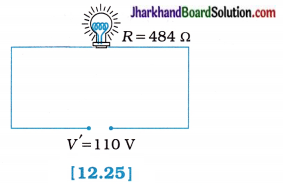
Now, the power consumed by the bulb when it is operated at 110 V is given by
P = \(\frac{V^{\prime 2}}{R}\)
= \(\frac{(110)^2}{484}=\frac{110 \times 110}{484}\)
= 25 W
Question 4.
Two conducting wires of the same material and of equal lengths and equal diameters are first connected in series and then parallel in a circuit across the same potential difference. The ratio of heat produced in series and parallel combinations would be-
(a) 1 : 2
(b) 2 : 1
(c) 1 : 4
(d) 4 : 1
Answer:
(c) 1 : 4
Hint: As both the wires are made of the same material and are of equal lengths and equal diameters, they have the same resistance R.
1. When they are connected in series their equivalent resistance Rs would be –
Rs = R + R = 2R
and when they are connected in parallel their equivalent resistance Rp is given by
\(\frac{1}{R_{\mathrm{p}}}=\frac{1}{R}+\frac{1}{R}=\frac{2}{R}\)
∴ Rp = \(\frac { R }{ 2 }\)
2. Now, heat produced in time t is H = \(\frac{V^2 t}{R}\). As here source voltage V is same,
When wires are connected in series,
Hs = \(\frac{V^2 t}{R_{\mathrm{s}}}=\frac{V^2 t}{2 R}\)
When wires are connected in parallel
∴ Hp = \(\frac{V^2 t}{R_{\mathrm{p}}}=\frac{V^2 t}{\left(\frac{R}{2}\right)}=\frac{2 V^2 t}{R}\)
The ratio of heat produced,
\(\frac{H_{\mathrm{s}}}{H_{\mathrm{p}}}=\frac{V^2 t}{2 R} \times \frac{R}{2 V^2 t}\) = \(\frac { 1 }{ 4 }\)
∴ Hs : Hp = 1 : 4
Question 5.
How is a voltmeter connected in the circuit to measure the potential difference between two points?
Answer:
A voltmeter is (always) connected in parallel across the points in the circuit between which the potential difference is to be measured.
Question 6.
A copper wire has diameter 0.5 mm and resistivity of 1.6 x 10⁻⁸ Ωm. What will be the length of this wire to make its resistance 10 Ω? How much does the resistance change if the diameter is doubled?
Solution:
We are given,
the diameter of the wire d = 0.5 mm = 0.5 x 10⁻³ m = 5 x 10⁻⁴ m
Resistivity of copper ρ = 1.6 x 10⁻⁸ Ω m
Required resistance R= 10 Ω
Length l = ?
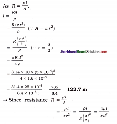
R ∝ \(\frac { 1 }{ d² }\) (If there is no change in p and L)
So, when diameter d is doubled, then resistance R becomes one-fourth of its original value.
Question 7.
The values of current I flowing in a given resistor for the corresponding values of potential difference V across the resistor are given below:
| I (amperes) | 0.5 | 1.0 | 2.0 | 3.0 | 4.0 |
| V (volts) | 1.6 | 3.4 | 6.7 | 10.2 | 13.2 |
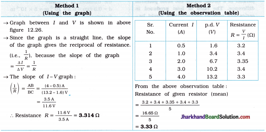
Plot a graph between V and I and calculate the resistance of that resistor.
Answer:
The graph between V and I plotted by using the given data is shown below:
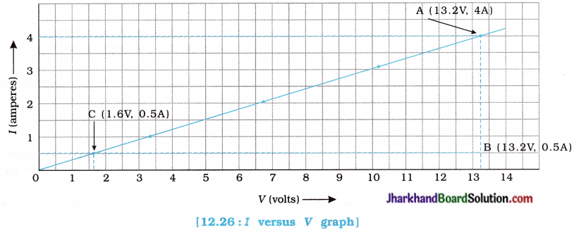
Calculation of the resistance of given resistor :
Question 8.
When a 12 V battery is connected across an unknown resistor, there is a current of 2.5 mA in the circuit. Find the value of the resistance of the resistor.
Solution:
Here, V = 12 V; I = 2.5 mA = 2.5 m A = 2.5 x 10⁻³ A; R = ?
The resistance of the resistor R = \(\frac { V }{ I }\)
= \(\frac { 1 }{ 2 }\)
= 4800 Ω
= 4.8 k Ω
Question 9.
A battery of 9 V is connected in series with resistors of 0.2 Ω, 0.3 Ω, 0.4 Ω, 0.5 Ω and 12 Ω respectively. How much current would flow through the 12 Ω resistor?
Solution:
Since all the given resistors are connected in series, their equivalent resistance Rs = 0.2 + 0.3 + 0.4 + 0.5 + 12 = 13.4 Ω The current through the circuit,
I = \(\frac{V}{R_{\mathrm{s}}}=\frac{9}{13.4}\) = 0.67 A
In a series combination, the same current I flows through all the resistors, so the current flowing through 12 Ω resistor = 0.67 A.
![]()
Question 10.
How many 176 Ω resistors (in parallel) are required to carry 5A on a 220V line?
Solution :
Here, I = 5 A; V = 220 V
So, the total resistance of the given circuit is
Rtotal = \(\frac { V }{ I }\) = \(\frac { 220 }{ 5 }\) = 44 Ω
i.e., when 44 Ω resistance is connected with 220 V line, 5 A current would flow through the given circuit.
Now, suppose ‘n’ resistors, each of resistance R, are required to be connected in parallel, so that the total resistance Rtotal becomes 44 Ω.
Hence, \(\frac{1}{R_{\text {total }}}=\frac{1}{R}+\frac{1}{R}\) + … n times
= \(\frac{1+1+\ldots n \text { times }}{R}=\frac{n}{R}\)
∴ Rtotal = \(\frac { R }{ n }\)
Now, Rtotal = 44 Ω and R = 176 Ω
So, 44 = \(\frac { 176 }{ 44 }\)
∴ n = \(\frac { 176 }{ 44 }\) = 4
Thus, 4 resistors each of 176 Ω connected in parallel will result in total resistance of 44 Ω causing a current of 5 A to flow when connected to 220 V line.
Question 11.
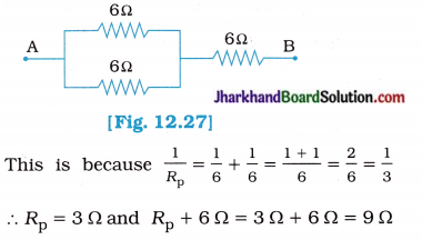
Show how you would connect three resistors, each of resistance 6 Ω, so that the combination has a resistance of (i) 9 Ω, (ii) 4 Ω.
Solution:
(i) In order to get a resistance of 9 Ω from three resistors, each of resistance 6 Ω, we connect two 6 Ω resistors in parallel and this parallel combination is connected in series with the third 6 Ω resistor as shown in the following figure:
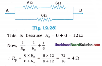
(ii) In order to get a resistance of 4 Ω from three resistors, each of resistance 6 Ω, we connect two 6 Ω resistors in series and this series combination is connected in parallel to the third 6 Ω resistor as shown in the following figure:
Question 12.
Several electric bulbs designed to be used on a 220 V electric supply line are rated 10W. How many bulbs can be connected in parallel with each other across the two wires of 220 V line if the maximum allowable current is 5 A?
Solution:
Here, the voltage rating of each bulb is 220 V and the power rating of each bulb is 10W.
So, the resistance of each bulb
R = \(\frac{V^2}{\rho}=\frac{220^2}{10}=\frac{220 \times 220}{10}\) = 4840 Ω
Now, here, V = 220 V and I = 5 A given.
So, the total resistance of the given circuit is
Rtotal = \(\frac { V }{ I }\) = \(\frac { 220 }{ 5 }\) = 44 Ω
i.e., When 44 Ω resistance is connected with 220 V line, 5 A current would flow through the given circuit.
Now, when ‘n’ bulbs each of resistance R, are connected in parallel, their equivalent
resistance Ptotal = \(\frac { R }{ n }\)
Hence, 44 = \(\frac { 4840 }{ 44 }\)
∴ n = \(\frac { 4840 }{ 44 }\) = 110
Thus, 110 bulbs each of resistance 4840 Ω connected in parallel will result in total resistance of 44 Ω causing a current of 5 A to flow, when connected to the 220 V line.
Question 13.
A hot plate of an electric oven connected to a 220 V line has two resistance coils A and B, each of 24 Ω resistance, which may be used separately, in series, or in parallel. What are the currents in the three cases?
Solution:
Here, the potential difference V = 220 V
The resistance of each coil RA = Rs = 24 Ω
(1) When each of the coils A or B is connected separately, the current through each coil is
I = \(\frac{V}{R_{\mathrm{A}}}\) or \(\frac{V}{R_{\mathrm{B}}}\)
= \(\frac { 220 }{ 24 }\)
= 9.166 A
(2) When the coils A and B are connected in series, the equivalent resistance of the circuit Rs = RA + RB = 24 + 24 = 48 Ω
So, the current through the series combination
Is = \(\frac{V}{R_{\mathrm{s}}}\)
= \(\frac { 220 }{ 48 }\)
= 4.58 A ≈ 4.6 A
(3) When the coils A and B are connected in parallel, the equivalent resistance Rp of the circuit is given by
\(\frac{1}{R_{\mathrm{p}}}=\frac{1}{R_{\mathrm{A}}}+\frac{1}{R_{\mathrm{B}}}=\frac{1}{24}+\frac{1}{24}=\frac{2}{24}\)
∴ Rp = 12 Ω
So, the current through the parallel combination
Ip = \(\frac{V}{R_{\mathrm{p}}}=\frac{220}{12}\) = 18.33 A
Question 14.
Compare the power used in the 2 Ω resistor in each of the following circuits:
(i) a 6 V battery in series with 1 Ω and 2 Ω resistors
(ii) a 4 V battery in parallel with 12 Ω and 2 Ω resistors.
Solution:
(i) As 1 Ω resistor and 2 Ω resistor are connected in series, the equivalent resistance Rs = 1 + 2 = 3 Ω
Now, the voltage of the battery V = 6 V
So, the current flowing through the circuit,
Is = \(\frac{V}{R_{\mathrm{s}}}=\frac{6}{3}\) = 2 A
In a series combination the same current 2 A flows through each resistor. Hence the current flowing through 2 Ω resistor is also 2 A.
∴ Power used in 2Ω resistor,
P1 = I²sR
= (2)² x 2 = 8 W
(ii) As 12 Ω resistor and 2 Ω resistor are connected in parallel and 4 V battery is connected in parallel with this parallel combination of resistors,
The p.d. across 2 Ω resistor will also be 4 V.
∴ Power used in 2 Ω resistor,
P2 = \(\frac{V^2}{R}=\frac{4^2}{2}=\frac{16}{2}\) = 8 W
In order to compare the power used in 2 Ω resistor in two different circuits, find the ratio of P1 and P2.
So, \(\frac{P_1}{P_2}=\frac{8}{8}\) = 1
∴ P1 = P2
Hence, 2 Ω resistor uses equal power, i.e., 8 W in both the circuits.
Question 15.
Two lamps, one rated 100 W at 220 V, and the other 60 W at 220 V are connected in parallel to electric mains supply. What current is drawn from the line if the supply voltage is 220 V?
Solution :
The resistance of 100 W lamp,
R1 = \(\frac{V^2}{P_1}=\frac{220^2}{100}=\frac{220 \times 220}{100}=\frac{4840}{10}\)Ω = 484 Ω
The resistance of 60 W lamp,
R2 = \(\frac{V^2}{P_2}=\frac{220^2}{60}=\frac{220 \times 220}{60}=\frac{4840}{6}\)Ω = 806.7 Ω
When, these lamps are connected in parallel, their equivalent resistance Rp is given by
\(\frac{1}{R_p}=\frac{1}{R_1}+\frac{1}{R_2}=\frac{R_2+R_1}{R_1 R_2}\)
∴ R<sub>p</sub> = \(\frac{R_1 R_2}{R_1+R_2}\)
= \(\frac{484 \times 806.7}{484+806.7}=\frac{390442.8}{1290.7}\) = 302. 6 Ω
The current drawn from the line,
I = \(\frac{V}{R_{\mathrm{p}}}=\frac{220}{302.6}\) = 0.7270 ≈ 0.73 A
Question 16.
Which uses more energy, a 250 W TV set in 1 h, or a 1200 W toaster in 10 minutes?
Solution:
For TV set:
Power P = 250 W = 250 \(\frac { J }{ s }\)
Time t = 1 h = 3600 s
Electric energy (used by TV set)
= P x t
= 250 \(\frac { J }{ 2 }\) x 3600 s
= 900000
= 900 kJ
For Toaster:
Power P = 1200 W = 1200\(\frac { J }{ s }\)
Time t = 10 minute = 10 x 60 = 600 s
Electric energy (used by toaster)
= P x t
= 1200 \(\frac { J }{ s }\) x 600 s = 720000 = 720 kJ s
From above calculations, it is clear that a 250 W TV set in 1 h consumes more electric energy than a 1200 W toaster in 10 minute.
![]()
Question 17.
An electric heater of resistance 8 Ω draws 15 A from the service mains for 2 hours. Calculate the rate at which heat is developed in the heater.
Solution :
Here, I = 15 A; R = 8 Ω; t = 2 h
The rate at which heat is developed in the
heater means its electric power,
P = I² R
= (15)² x 8 = 225 x 8 = 1800 W = 1800 \(\frac { J }{ s }\)
Question 18.
Explain the following:
(a) Why is the tungsten used almost exclusively for filament of electric lamps?
(b) Why are the conductors of electric heating devices, such as bread-toasters and electric irons, made of an alloy rather than a pure metal?
(c) Why is the series arrangement not used for domestic circuits?
(d) How does the resistance of a wire vary with its area of cross-section?
(e) Why are copper and aluminium wires usually employed for electricity transmission?
Answer:
(a) Because tungsten has a high melting point (3380 °C), It does not melt at high temperature. It retains as much of heat generated, so that it becomes very hot and emits light without melting away.
Moreover, tungsten has high flexibility and low rate of evaporation at high temperature. That is the reason why tungsten is used as filament of electric lamps.
(b) The coils of electrical heating devices such as electric toasters and electric irons are made of an alloy, e.g., Nichrome rather than a pure metal because :
- the resistivity of an alloy e.g., Nichrome is much higher than that of its constituent metals, c
- alloys do not oxidise (i.e., burn) readily at high temperature (i.e., when it is red hot at 800 °C)
alloy has a high melting point.
(c) (1) In a series circuit the current is constant throughout the electric circuit. So it s is obviously impracticable to connect an electric
bulb and an electric heater in series because they need currents of widely different values to operate properly.
(2) In a series circuit when one component (or electrical appliance) fails due to some defect, the circuit is broken and none of the components (or electrical appliances) works.
(3) In a series circuit all the electrical appliances have only one switch due to which they cannot be turned ON or OFF separately.
(4) In a series circuit electrical appliances of different power ratings do not get the same voltage (220V) as that of the power supply line because the voltage is shared by all the appliances. The appliances get less voltage and hence do not work properly.
(d) The resistance of a wire is inversly proportional to its area of cross-section
i.e., R ∝ \(\frac { 1 }{ A }\)
Thus, if the wire is thick (large area of cross-section), then its resistance is less. If the wire is thin (less area of cross-section), then its resistance is large.
(e) Because:
- Copper and aluminium have low electric resistivity, so they conduct electric current without heavy heat losses (due to which they are known as very good conductors of electricity).
- Copper and aluminium are much more easily and cheaply available as compared to metal like silver.
They can be easily made into wires due to high malleability.
Therefore, copper and aluminium wires are usually employed for electricity transmission.
Jharkhand Board Class 10 Science Electricity InText Questions and Answers
Question 1.
What does an electric circuit mean?
Answer:
An electric circuit is a continuous and closed path of an electric current.
OR
A continuous and closed path consisting of conducting wires and other electrical components along which an electric current flows is called an electric circuit.
Question 2.
Define the unit of current.
Answer:
The SI unit of current is called an ampere (A).
If 1 coulomb charge flows through any cross-section of a conductor in 1 second, then the electric current flowing through the conductor is
said to be 1 ampere.
i.e., 1 A = \(\frac { 1C }{ 1s }\) = 1C s-1
Question 3.
Calculate the number of electrons constituting one coulomb of charge.
Solution :
We know that one electron possesses a negative charge of 1.6 x 10⁻¹⁹ C.
i.e., charge on 1 electron = – 1.6 x 10⁻¹⁹ C
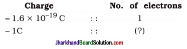
∴ No. of electron constituting – 1 C of charge
= \(\frac{-1 C \times 1}{-1.6 \times 10^{-19} \mathrm{C}}\)
= \(\frac { 10 }{ 1.6 }\) x 1018 = 6.25 x 10¹⁸
Thus, 6.25 x 10¹⁸ electrons taken together constitute 1 coulomb of charge.
In other words, the SI unit of electric charge coulomb (C) is equivalent to the charge contained in 6.25 x 10¹⁸ electrons.
Question 4.
Name a device that helps to maintain a potential difference across a conductor.
Answer:
An electric cell or battery is a device that helps to maintain a potential difference across a conductor.
Question 5.
What is meant by saying that the potential difference between two points is 1 V?
Answer:
The potential difference between two points (in a electric field) is said to be 1 volt if 1 J of work is done to move a charge of 1 C from one point to another point.
1 V = \(\frac { 1 J}{ 1 C }\)
Question 6.
How much energy is given to each coulomb of charge passing through a 6 V battery?
Solution:
Here the term, ‘each coulomb’ means ‘every 1 coulomb’. So Q = 1 coulomb, potential difference V = 6 volt, Energy = work done, W = ?
Now, W = VQ
= 6V x 1C
= 6 J
Since the work done on each coulomb of charge is 6 J, 6 J energy is given to each coulomb of charge passing through a 6V battery.
Question 7.
On what factors does the resistance of a conductor depend?
Answer:
The resistance R of a conductor depends on :
- its length l as R ∝ l
- its area of cross-section (i.e., thickness of the conductor) as R ∝ \(\frac { 1 }{ A }\)
- the nature of the material of the conductor (i.e., resistivity of material of the conductor)
- its temperature
Question 8.
Will current can flow more easily through a thick wire or a thin wire of the same material, when connected to the same source? Why?
Answer:
The current will flow more easily through a thick wire than through a thin wire of the s same material and having the same length when connected to the same source.
- Because, the resistance of a wire is inversly proportional to its area of cross-section, A thick wire has more area of cross-section and hence less resistance compared to a thin wire provided the two wires have the same length.
- Hence, a current can flow more easily through a thick wire compared to a thin wire when connected to the same source.
Question 9.
Let the resistance of an electrical component remain constant while the protential difference across the two ends of the component decreases to half of its former value. What change will occur in the current through it?
Answer:
According to Ohm’s law, I = \(\frac { V }{ R }\)
Here, as R = constant, I ∝ V.
So, when the potential difference across the two ends of the electrical component decreases to half of its former value, the current through it will also decreases to half of its former value.
![]()
Question 10.
Why are coils of electric toasters and electric irons made of an alloy rather than a pure metal?
Answer:
The coils of electrical heating devices such as electric toasters and electric irons are made of an alloy, e.g., Nichrome rather than a pure metal because :
- the resistivity of an alloy e.g., Nichrome is much higher than that of its constituent metals.
- alloys do not oxidise (i.e., burn) readily at high temperature (i.e., when it is red hot at 800 °C)
- alloy has a high melting point.
Question 11.
Use the data in Table 2 to answer the following:
(a) Which is a better conductor, iron or mercury?
(b) Which material is the best conductor?
Answer:
(a) The electrical resistivity of iron is 10.0 x 10⁻⁸ Ω m whereas that of mercury is 94.0 x 10″8fim. As the resistivity of iron is less than that of mercury, iron (Fe) is a better conductor than mercury (Hg).
(b) Silver metal has the lowest electrical resistivity of 1.60 x 10⁻⁸ Ω m, therefore silver metal is the best conductor of electricity.
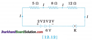
Question 12.
Draw a schematic diagram of a circuit consisting of a battery of three cells of 2 V each, a 5Ω resistor, an 8 Ω resistor, and a 12 Ω resistor, and a plug key, all connected in series.
Answer:
A schematic diagram of a circuit consisting of a battery of three cells of 2 V each, a 5 Ω resistor, an 8 Ω resistor, and a 12 Ω resistor, and a plug key, all connected in series is shown in figure 12.12
Question 13.
Redraw the circuit of putting in an ammeter to measure the current through the resistors and a voltmeter to measure the potential difference across the 12 Ω resistor. What would he the readings in the ammeter and the voltmeter?
Answer:
The circuit diagram of above with an ammeter A and a voltmeter V across 12 Ω resistor is shown in figure 12.13.
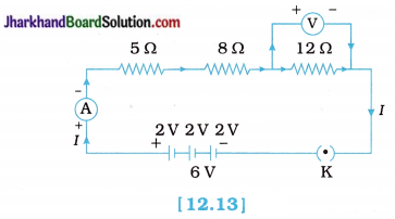
Calculation of current flowing in the circuit:
Equivalent resistance of the circuit,
Rs = 5 Ω + 8 Ω + 12 Ω = 25 Ω
Potential difference V = 6 volt
In a series combination, the current flowing through each resistor is the same and equal to the total current flowing through the circuit.
∴ Current through the resistors,
I = \(\frac { V }{ R }\)
= \(\frac { 6 }{ 25 }\)
= 0.24 A
Since the current in the circuit and the current through each resistor is the same, the ammeter will show a reading of 0.24 A.
Calculation of potential difference across 12 Ω resistor:
As total current 0.24 A flows in the circuit, the same current 0.24 A would also flow through the 12 Ω resistor which is connected in series.
∴ The potential difference across the 12 Ω resistor,
V = IR
= 0.24 x 12 = 2.88 V
Thus, the p.d. across 12 Ω resistor is 2.88 volt.
So, the voltmeter will show a reading of 2.88 V.
Question 14.
Judge the eΩuivalent resistance when the following are connected in parallel:
(a) 1 Ω and 106 Ω
(b) 1 Ω, 10³ Ω and 106Ω
Answer:
(a) Less than 1 Ω (but approximately 1 Ω)
(b) less than 1 Ω (but approximately 1 Ω)
Explanation: When resistors are connected in parallel, the equivalent resistance is less than the least resistance (here in both the cases it is 1 Ω) connected in the combination.
or
(a) Here, R1 = 1 Ω and R2 = 106 Ω
The equivalent resistance Rp of the parallel combination is given by,
\(\frac{1}{R_{\mathrm{p}}}=\frac{1}{R_1}+\frac{1}{R_2}\)
∴ Rp = \(\frac{R_1 \times R_2}{R_1+R_2}\)
= \(\frac{1 \times 10^6}{1+10^6}\)
= \(\frac { 1000000 }{ 1000001 }\) ≈ 1 Ω
(b) Here, R1 = 1 Ω, R2 = 10³ Ω and R3 = 106
The equivalent resistance Rp of the parallel combination is given by,
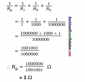
Question 15.
An electric lamp of 100 Ω, a toaster of resistance 50 Cl, and a water filter of resistance 500 Ω are connected in parallel to a 220 V source. What is the resistance of an electric iron connected to the same source that takes as much current as all three appliances and what is the current through it?
Solution :
Here, Resistance of an electric lamp R1 = 100 Ω
Resistance of a toaster R2 = 50 Ω
Resistance of a water filter R3 = 500 Ω.
Equivalent resistance Rp of three resistors R1, R2 and R3 connected in parallel is given by,
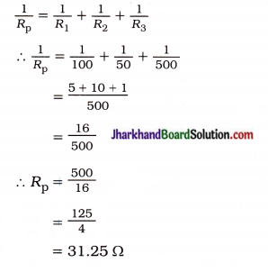
Total current through the circuit (i.e., through all the three appliances)
I = \(\frac{V}{R_p}\)
= \(\frac { 220 }{ 31.25 }\)
= 7.04 A
Since the electric iron connected to the same source (i.e., 220 V) takes as much current as taken by all the three appliances (i.e., f = 7.04A), its resistance must be equal to Rp.
So, the resistance of the electric iron = 31.25 Ω
and the current through the electric iron = 7.04 A
Question 16.
What are the advantages of connecting electrical devices in parallel with the battery instead of connecting them in series?
Answer:
The advantages of connecting electrical devices in parallel with the battery instead of connecting them in series are as follows :
(1) A parallel combination / circuit is helpful when each device has different resistance and requires different current for its operation, as in this case the total resistance of the circuit is reduced due to which the current from the battery is high and hence each electrical device can draw the required amount of current.
This is not so in a series combination / circuit because total resistance increases too much in series circuit due to which the current from the battery is low and the same low current flows through all the devices, irrespective of their resistances and hence devices cannot work properly.
(2) In a parallel combination / circuit each electrical device gets the same p.d. (potential difference) across it as that of the battery due to which all the devices work properly.
While in case of a series combination / circuit the devices do not get the same p.d. as that of the battery because the p.d. is shared by all the devices connected in series.
(3) In a parallel combination / circuit if one electrical device stops working due to some defect, then other devices are not affected. They continue to work without any problem.
On the other hand, in a series combination/ circuit if one electrical device stops working due to some defect, then all other devices also stop working as the whole circuit is broken.
(4) In a parallel combination / circuit each electrical device has its own switch due to which it can be turned ‘ON’ or turned ‘OFF’ independently without affecting other devices.
But in a series combination / circuit all the electrical devices have only one switch due to which they cannot be turned ‘OFF’ or turned ‘ON’ independently.
Question 17.
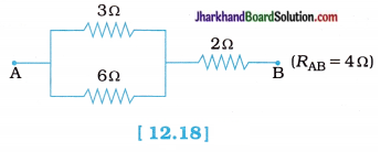
How can three resistors of resistances 2 Ω, 3 Ω and G Ω be connected to give a total resistance of (a) 4 Ω, (b) 1 Ω?
Answer:
(a) In order to obtain a total resistance of 4 Ω from three resistors of 2 Ω, 3Ω and 6Ω…
1. First connect the two resistors of 3 Ω and 6 Ω in parallel to get a total resistance of 2 Ω. This is because in parallel combination,
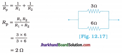
2. Now, above parallel combination of 3 Ω and 6 Ω resistors is connected in series with the remaining 2 O resistor to get total resistance of 4 Cl. This is because in series combination.
Rs = Rp + R3
= 2 + 2
= 4 Ω
Hence, the arrangement of three resistors 2 Ω, 3 Ω and 6 Ω which gives total resistance 4 Ω can be represented as follows :
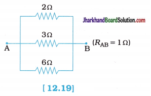
(b) In order to obtain a total resistance of 1 Ω from three resistors of 2 Ω, 3 Ω and 6 Ω, all the three resistors should be connected in parallel. This is because in a parallel combination,
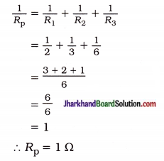
Hence, the arrangement of three resistors 2 Ω, 3 Ω and 6 Ω which gives total resistance 1 Ω can be represented as follows :
Question 18.
What is (a) the highest, (b) the lowest total resistance that can be secured by combinations of four coils of resistances 4 Ω,
8 Ω, 12 Ω, 24 Ω?
Solution:
(a) The highest resistance can be secured (or obtained) by connecting all the four coils in series. In this case,
Rs = R1+R2 + R3 + R4
= 4 + 8 + 12 + 24 = 48 Ω
Thus, the highest resistance which can be secured is 48 Ω.
(b) The lowest resistance can be secured by connecting all the four coils in parallel. In this cae,
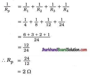
Thus, the lowest resistance which can be secured is 2 Ω.
Question 19.
Why does the cord of an electric heater not glow while the heating element does?
Answer:
The heating element of an electric heater is made of an alloy (such as Nichrome) which has high resistance (partly due to high resistivity) whereas the cord is made of copper metal which has very low resistance (partly due to low resistivity).
- Now, the heating element of an electric heater made of Nichrome glows because it becomes red-hot due to the large amount of heat (according to H = I²Rt) is produced on passing current.
- On the other hand, the connecting cord of the electric heater made of copper does not glow because relatively very less (negligible) heat (according to H = I²Rt) is produced in it by passing the same current.
![]()
Question 20.
Compute the heat generated while transferring 96000 coulomb of charge in one hour through a potential difference of 50 V.
Solution:
Here, charge, Q = 96000 C,
time t = 1 h = 60 x 60 = 3600 s,
potential difference V = 50 V
Now,
Heat generated H = VIt
= V(\(\frac { Q }{ t }\))t (∵ I = \(\frac { Q }{ t }\))
= 50 x 96000
= 4800000 J
= 4.8 x 10⁶ J
or
= 4.8 x 10³ x 10³ J
= 4.8 x 10³ kJ
= 4800 kJ
Question 21.
An electric iron of resistance 20 Ω takes a current of 5 A. Calculate the heat devloped in 30 s.
Solution :
Here, current I = 5 A,
resistance R = 20 Ω, time t = 30 s
Now,
Heat produced H = I²Rt
= (5)² x 20 x 30
= 25 x 20 x 30
= 15000 J
= 15 kJ
Question 22.
What determines the rate at which energy is delivered by a current?
Answer:
The electric power of the source determines the rate at which energy is delivered by the current to the load / appliance.
[Whereas the electric power of an appliance determines the rate at which energy delivered by a current Is consumed by appliance.]
Question 23.
An electric motor takes 5 A from a 220 V line. Determine the power of the motor and the energy consumed in 2h.
Solution:
Here, I = 5A, V = 220V,
t = 2h = (2 x 60 x 60)s = 7200s
Power P = VI = 220 x 5 = 1100W = 1100J/s
Now,
Energy consumed W = Pt = 1100J/s x 7200s
= 7920000
= 7.92 x 10⁶J
OR
Energy consumed W = Pt = 1100 w x 2 h
= 2200 Wh
= 2.2 x 10³ Wh
= 2.2 k Wh
Activity 12.1 [T. B. Pg. 203]
To verify Ohm’s law.
OR
To find the relationship between potential difference (V) and current (I).
Procedure:
1. Set up a circuit as shown in figure 12.3, consisting of a +Nichrome wire XY of length say 0.5 m, an ammeter, a voltmeter and four cells of 1.5 V each.
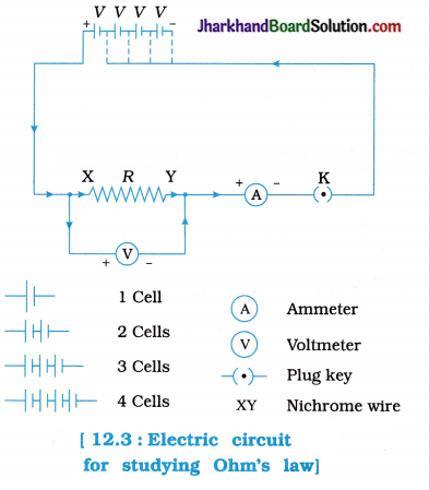
2. First use only one cell as the source in the circuit.
Note the reading of ammeter I, for the current and reading of the voltmeter V for the potential difference across the Nichrome wire XY in the circuit.
Tabulate them in the Table given.
3. Next connect two cells in the circuit and note the respective readings of the ammeter and voltmeter for the values of current through the Nichrome wire and potential difference across the Nichrome wire.
4. Repeat the above steps using three cells and then four cells in the circuit separately.
Calculate the ratio V to I for each pair of potential difference V and current I.
Observation table :
| Sr. No. | Number of cells used in the circuit | Potential difference across the Nichrome wire V (volt) | Current through the Nichrome wire I (ampere) | \(\frac { V }{ I }\) (volt / ampere) |
| 1. | 1 | 1.5 | 0.1 | 15 |
| 2. | 2 | 3 | 0.2 | 15 |
| 3. | 3 | 4.5 | 0.3 | 15 |
| 4. | 4 | 6 | 0.4 | 15 |
Plot a graph between V and I and observe the nature of the graph.
(Take the voltage (V) on X-axis and the current (J) on Y-axis. Draw the graph of I-V taking proper scale.)
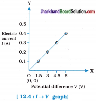
Observation:
When V increases I also increases linearly, i.e., I ∝ V. The ratio V/I is found to be (approximately) the same, i.e., 15V/A.
The graph between V and 1 is a straight line passing through the origin O.
Conclusion:
The electric current flowing through a metallic wire is directly proportional to the potential difference across its ends (J ∝ V) and V/I is a constant ratio in particular case.
Activity 12.2 [T. B. Pg. 205]
To show that the strength of an electric current in a circuit depends on resistance used in it.
Procedure:
1. Take a Nichrome wire, a torch bulb, a low bulb (10W) and an ammeter (0-5A range), a plug key and some connecting wires.
2. Set up the circuit by connecting four dry cells of 1.5 V each in series with the ammeter leaving a gap XY in the circuit, as shown in figure 12.5.
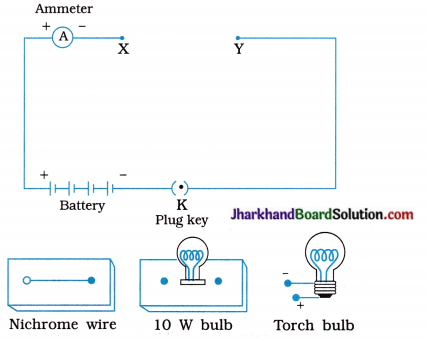
3. Complete the circuit by connecting the Nichrome wire in the gap XY. Plug the key.
Note down the ammeter reading. Take out the key from the plug after measuring the current through the circuit.
[Note: Always take out the key from the plug after measuring the current through the circuit.]
4. Replace the Nichrome wire with the torch bulb in the circuit and find the current through it by measuring the reading of the ammeter.
5. Now repeat the above step with the 10 W bulb in the gap XY.
- Are the ammeter readings different for different s components connected in the gap XY?
- What do the above observations indicate?
6. You may repeat this Activity by keeping any material component in the gap.
Observe the ammeter readings in each case. Analyse the observations.
Observation :
- Yes, the ammeter readings are different for different components (Nichrome wire, a torch bulb and a low bulb) when connected in the gap XY.
- If we take any other material component in the gap XY, the reading of the ammeter may be different.
- This is because certain components offer an easy path for the flow of electric current while the others resist the flow.
- i.e., the current through an electric component depends on its resistance.
Conclusion :
The strength of an electric current in a circuit depends on the resistance used in it.
- A component of a given size that offers low resistance is called a good conductor.
- A component of the same size which offers appreciable resistance is called a resistor.
- A component of the same size that offers a higher resistance is called a poor conductor or a bad conductor.
- A component of the same size that offers very high resistance is called an insulator.
Activity 12.3 [T. B. Pg. 206]
To study the factors on which resistance of conducting wire depends.
Procedure:
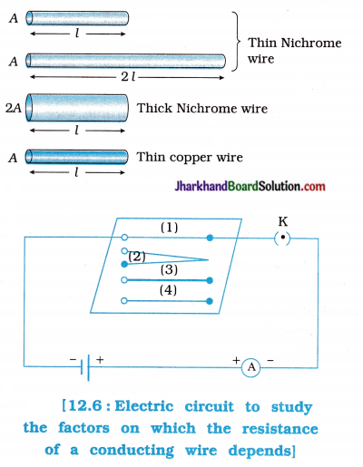
- Complete an electric circuit consisting of a cell, an ammeter, a Nichrome wire of length l [say, marked (1)] and a plug key, as shown in figure 12.6.
- Now, plug the key. Note the current in the ammeter.
- Replace the Nichrome wire by another Nichrome wire of same thickness but twice the length, that is 21 [marked (2) in the figure],
- Note the ammeter reading.
- Now replace the wire by a thicker Nichrome wire, of the same length l [marked (3)]. A thicker wire has a larger cross-sectional area. Again note down the current through the circuit.
- Instead of taking a Nichrome wire, connect a copper wire [marked (4) in the figure] in the circuit.
- Let the wire be of the same length and same area of cross-section as that of the first Nichrome wire [marked (1)]. Note the value of the current.
- Notice the difference in the current in all cases,
- Does the current depend on the length of the conductor ?
- Does the current depend on the area of s cross-section of the wire used ?
Observations :
- Ammeter shows the current I flows in the Nichrome wire marked (1).
- When the length of Nichrome wire marked (2) is doubled keeping its same thickness (i.e., when the Nichrome wire marked (1) is replaced by the Nichrome wire marked (2) the ammeter reading decreases to half, i.e. current becomes 1/2.
- When the thickness of Nichrome wire marked (3) is increased keeping its length same i.e., when the Nichrome wire marked (3) is S connected in the circuit), the ammeter reading increases, i.e., current I increases.
- When Nichrome wire is replaced by a copper s wire marked (4) of same length and same cross-sectional area as marked (1), the ammeter reading increases, i.e., current I increases.
Conclusion :
- Resistance of the conducter depends on its s length. Here resistance of wire R is directly proportional to length l, i.e., R ∝ l.
- Resistance of the conductor depends on its area of cross-section. Here resistance of wire R is inversely proportional to area of cross-section A, i.e., R ∝ \(\frac { 1 }{ 2 }\)
- Copper is a better conductor than Nichrome. Resistance of wire depends on the nature of S its material.
Activity 12.4 [T. B. Pg. 210]
To study the series combination of resistors.
Procedure :
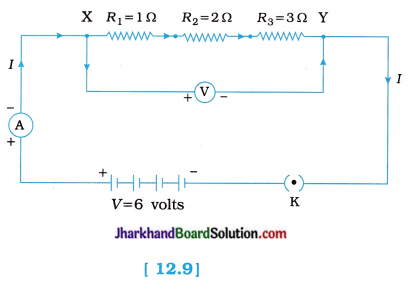
- Join three resistors of different values in series. Connect them with a battery, an ammeter and a plug key, as shown in figure 12.9.
- You may use the resistors of values like 1 Ω, 2 Ω, 3 Ω, etc. and a battery of 6 V for performing this Activity.
- Plug the key. Note the ammeter reading. [part (1)]
- Change the position of the ammeter to anywhere inbetween the resistors. Note the ammeter reading each time, [part (2)]
- Do you find any change in the value of current through the ammeter?
Observation :
- The ammeter reading is nearly 1 A.
- When the position of the ammeter is changed to anywhere inbetween the resistors, its reading remains the same, i.e., the current flowing through it and through each part of the circuit, i.e., through each resistor is the same.
- No, current flowing through the ammeter does not change.
Conclusion :
- The value of the current in the ammeter is the same, independent of its position in the electric circuit.
- In a series combination of resistors the current is the same in every part of the circuit, i.e., the same current flows through each resistor. This is due to the reason that, the current has only one path to flow.
Important note:
(1) In discussion of Activity 12.4, ammeter and voltmeter are considered as ideal meters. (2) Ideally, an ammeter should have zero resistance and a voltmeter should have infinite resistance. But in practice, these conditions cannot be realized and hence practically the voltmeter draws some current from the main branch and so the ammeter reading in part (2) is slightly less than that in part (1).
![]()
Activity 12.5 [T. B. Pg. 211]
To show that in a series combination of resistors, the total potential difference across the combination divides itself across the individual resistors.
Procedure:
- In Activity 12.4, insert a voltmeter across the ends X and Y of the series combination of three resistors, as shown in figure 12.7.
- Plug the key in the circuit and note the voltmeter reading. It gives the potential difference across the series combination of resistors. Let it be V.
- Now measure the potential difference across the two terminals of the battery. Compare the two values.
- Take out the plug key and disconnect the voltmeter. Now insert the voltmeter across the ends X and P of the first resistor, as shown
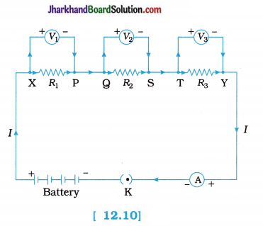
- Plug the key and measure the potential difference across the first resistor. Let it be V1
- Similarly, measure the potential difference across the other two resistors, separately. Let these values be V2 and V3, respectively.
- Deduce a relationship between V, V1, V2 and V3.
Observation:
- The p.d. across the series combination is equal to the p.d. across the two terminals of the battery.
- p.d. across the first resistor R1 is found out to be V1 using voltmeter.
- Similarly with the help of voltmeter, p.d. across resistors R2 and R3 separately are found out to be V2 and V3 respectively.
- It is found out that V = V1 + V2 + V3.
Conclusion:
- In a series combination of different resistors, the potential difference across different resistors is different, i.e., If R1 ≠ R2 ≠ R3, V1 ≠ V2 ≠ V3.
- The total p.d. across the combination is equal to the sum of p.d. across each of the resistors, i.e., total p.d. across the combination divides itself across the individual resistors, i.e., V is equal to V1 + V2 + V3.
Important note:
In Activity 12.5 it is assumed that, R (ammeter) = zero and R (voltmeter) = ∞, so V1 + V2 + V3, In practice, these conditions cannot be realized, hence practically V is (very nearly) equal to V1 + V2 + V3.
Activity 12.6 [T. B. Pg. 213]
To study the parallel combination of resistors.
OR
To study the relationship between potential difference and respective resistance in parallel circuit as well as the relationship between s current and respective resistance in parallel circuit.
Procedure:
1. Make a parallel combination XY of three resistors having resistances R1, R2 and R3, respectively. Connect it with a battery, a plug key and an ammeter, as shown in figure 12.14. Also connect a voltmeter in parallel with the combination of resistors.
2. Plug the key and note the ammeter reading. (Let the current be I).
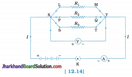
3. Also take the voltmeter reading. (It gives the potential difference V, across the combination).
4. Connect a voltmeter across the resistor with resistance R1 and note the voltmeter reading V1 (see figure 12.14).
5. Similarly connect a voltmeter across the resistors with resistances R2 and R3 separately and note s the corresponding voltmeter readings V2 and V3.
6. Take out the plug from the key. Remove the ammeter and voltmeter from the circuit.
7. Insert the ammeter in series with the resistor s with resistance R1, as shown in figure 12.15. Note the ammeter reading, I1.
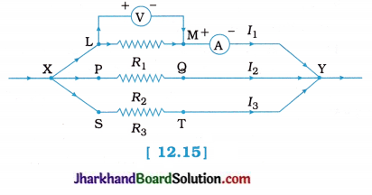
8. Similarly, measure the current through the resistors with resistances R2 and R3. Let these be I2 and I3, respectively.
What is the relationship between I, I1, I2 and I3?
Observations :
- Ammeter showed the reading I when connected as shown in figure 12.14.
- Voltmeter showed reading V when connected as shown in figure 12.14.
- It is found that the p.d. across each resistor is the same (i.e., V), as across the combination of resistors, i.e., V1 = V2 = V3 = V
- Ammeter showed reading I1, when connected with the resistor R1 as shown in figure 12.15.
- Similarly ammeter showed reading I2 and I3 measured separately through R2 and R3 respectively.
- The relationship between I, I1, I2 and I3 is:
I = I1 + I2 + I3
Where, I = Total current through the combination of resistors in parallel
I1, I2, I3 = Currents through R1, R2 and R3 respectively.
Conclusion:
- In parallel combination of resistors, the potential difference across different resistances will be same.
- Total current I in the given parallel circuit is divided amongst different resistors.