Jharkhand Board JAC Class 10 Science Solutions Chapter 13 Magnetic Effects of Electric Current Textbook Exercise Questions and Answers.
JAC Board Class 10 Science Solutions Chapter 13 Magnetic Effects of Electric Current
Jharkhand Board Class 10 Science Magnetic Effects of Electric Current Textbook Questions and Answers
Question 1.
Which of the following correctly describes the magnetic field near a long straight wire?
(a) The field consists of straight lines perpendicular to the wire.
(b) The field consists of straight lines parallel to the wire.
(c) The field consists of radial lines originating from the wire.
(d) The field consists of concentric circles centred on the wire.
Answer:
(d) The field consists of concentric circles centred on the wire.
Hint: This is an experimental fact. Which is only exhibited by the right-hand thumb rule.
Question 2.
The phenomenon of electromagnetic induction is…
(a) the process of charging a body.
(b) the process of generating magnetic field due to a current passing through a coll.
(c) producing induced current in a coil due to relative motion between a magnet and the coil.
(d) the process of rotating a coil of an electric motor.
Answer:
(c) producing induced current in a coil due to relative motion between a magnet and the coil.
Question 3.
The device used for producing electric current is called a…
(a) generator.
(b) galvanometer.
(c) ammeter.
(d) motor
Answer:
(a) generator.
Hint: A generator converts mechanical energy into electrical energy.
Question 4.
The essential difference between an AC generator and a DC generator is that…
(a) an AC generator has an electromagnet while a DC generator has permanent magnet.
(b) a DC generator will generate a higher voltage.
(c) an AC generator will generate a higher voltage.
(d) an AC generator has slip rings while the DC generator has a commutator.
Answer:
(d) an AC generator has slip rings while the DC generator has a commutator.
[Due to the slip rings, the direction of the current produced by an AC generator is reversed at regular interval of time, while the current produced by a DC generator always flows in one direction.]
![]()
Question 5.
At the time of short circuit, the current in the circuit…
(a) reduces substantially.
(b) does not change.
(c) increases heavily.
(d) varies continuously.
Answer:
(c) increases heavily.
Question 6.
State whether the following statements are true or false :
(a) An electric motor converts mechanical energy into electrical energy.
(b) An electric generator works on the principle of electromagnetic induction.
(c) The magnetic field lines at the centre of a long circular coil carrying current are parallel straight lines.
(d) The wire with green insulation is usually the live wire of an electric supply.
Answer:
(a) False
[An electric motor converts electrical energy into mechanical energy.]
(b) True
(c) True
(d) False
[The wire with green insulation is the earth wire, whereas the wire with red insulation is the live wire of an electric supply.]
Question 7.
List two methods of producing magnetic fields.
Answer:
Magnetic fields can be produced by passing an electric current through:
- a straight conductor
- a circular loop and
- a solenoid.
Question 8.
How does a solenoid behave like a magnet? Can you determine the north and south poles of a current-carrying solenoid with the help of a bar magnet? Explain.
Answer:
- A current-carrying solenoid behaves like a bar magnet and the polarities of its ends depend upon the direction of the current through it.
- Yes, we can use a bar magnet to determine the north and south poles of a current-carrying solenoid.
- In order to determine the magnetic poles of a current-carrying solenoid, place it in a brass hook and suspend it with a long thread so that it can moves freely in a horizontal plane.
Bring the north pole of a bar magnet near one of its ends. If that end of the solenoid moves towards the bar magnet, then it must be its south pole and the other end its north pole, On the contrary if that end of the solenoid moves away from the magnet, then it must be its north pole and the other end its south pole.
Question 9.
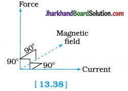
When is the force experienced by a current carrying conductor placed in a magnetic field largest?
Answer:
The force experienced by a current-carrying conductor placed in a magnetic field is the largest, when the current in the conductor is perpendicular to the magnetic field.
For reference see the following figure :
Question 10.
Imagine that you are sitting in a chamber with your back to one wall. An electron beam, moving horizontally from back wall towards the front wall, is deflected by a strong magnetic field to your right side. What is the direction of magnetic field?
Answer:
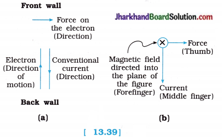
- For reference, see figure (a) and (b).
- The direction of the conventional current is opposite to the direction of motion of the electron.
- Applying Fleming’s left-hand rule, we find that when the middle finger points in the direction of the current and the thumb points in the direction of the force, the forefinger points downward giving the direction of the magnetic field.
[Note : IMg indicates a vector (arrow) going into the plane of figure, while IMG indicates a vector (arrow) coming out of the plane of the figure.]
Question 11.
Draw a labelled diagram of an electric motor. Explain its principle and working. What is the function of the split ring in an electric motor?
Answer:
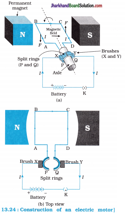
Construction: The construction of an electric motor is as shown in figure 13.24.
- Electric motor consists of a rectangular coil ABCD of insulated copper wire.
- The coil is placed between the two poles of a permanent magnet such that the arms AB and CD are perpendicular to the direction of the magnetic field.
- The ends of the coil are connected to two halves P and Q of a split ring.
- The inner sides of these halves are insulated and attached to an axle such that they can rotate easily on it.
- The external conducting edges of P and Q touch two conducting stationary brushes (i.e., carbon strips) X and Y respectively.
- These brushes are connected to a plug key and battery as shown in figure 13.24.
Working:
(1) Current in coil ABCD enters from the source – battery through conducting brush X and flows back to the battery through brush Y.
(2) Current in arm AB of the coil flows from A to B while in arm CD it flows from C to D, i.e., opposite to the direction of the current through AB. Both the currents flowing in AB and CD are perpendicular to the magnetic field.
(3) On applying Fleming’s left hand rule for finding the direction of the force on a current carrying conductor in a magnetic field (see figure 13.24), we find that the force acting or arm AB pushes it downwards while the force acting on arm CD pushes it upwards. These forces are also equal in magnitude and perpendicular to the respective lengths of arms AB and CD.
(4) So, the coil and the axle, mounted free to turn about an axis, rotate anticlockwise.
(5) At half rotation, Q makes contact with brush X and P with brush Y. Therefore, the current in the coil gets reversed and flows along the path DCBA.
(6) A device that reverses the direction of flow of current through a circuit is called a commutator.
In an electric motor the split rings act as a commutator.
(7) Now, the reversal of current also reverses the direction of the force acting on the arms AB and CD. Thus arm AB that was earlier pushed down, is now pushed up and arm CD previously pushed up, is now pushed down.
(8) Therefore, the coil and the axle rotate half a turn more in the same direction.
(9) The reversing of the current is repeated at each half rotation, giving rise to a continuous rotation of the coil and the axle.
Important note : When currents through arms BC and DA are either parallel or antiparallel to the magnetic field, magnetic force does not act on them.
When a rectangular coil carrying a current is placed in a magnetic field, then forces, equal in magnitude and opposite in direction, act on its two parallel sides, perpendicular to their lengths, due to which the coil rotates continuously.
The function of the split ring : Due to the split ring commutator in an electric motor, the direction of the current through the coil is reversed after every half rotation of the coil. This reverses the direction of the force acting on the two arms of the coil. The arm that was earlier pushed downward is now pushed upward, while the other arm is now pushed downward. Therefore, the coil continues to rotate in the same direction.
![]()
Question 12.
Name some devices in which electric motors are used.
Answer:
Electric motors are used in electric fans, refrigerators, mixers and grinders, washing machines, water-pumps, coolers, etc.
Question 13.
A coil of insulated copper wire is connected to a galvanometer. What will happen if a bar magnet is (i) pushed into the coil, (ii) withdrawn from inside the coil, (iii) held stationary inside the coil?
Answer:
(i) The galvanometer will show a momentary deflection in one direction. It means a current is induced in the coil in one direction due to the relative motion between the coil and the magnet.
(ii) The galvanometer will show a momentary deflection in the opposite direction. It means a current is induced in the coil in the opposite direction due to the relative motion between the coil and the magnet.
(iii) There will be no deflection in the galvanometer. It means no current is induced in the coil, as there is no relative motion between the coil and the magnet.
[Note: The greater the speed of the magnet, the greater is the deflection of the pointer in the galvanometer.]
Question 14.
Two circular coils A and B are placed close to each other. If the current in coil A is changed, will some current be induced in coil B? Give reason.
Answer:
Yes. Current will be induced in coil B. Reason : When the current in coil A is changed, the magnetic field around it changes.
As the two circular coils (with their planes parallel to each other) are placed close to each other, the magnetic field lines linked with coil B also change. Therefore, some current is induced in coil B.
Question 15.
State the rule to determine the direction of a (i) magnetic field produced around a straight conductor-carrying current, (ii) force experienced by a current-carrying straight conductor placed in a magnetic field which is perpendicular to it, and (iii) current induced in a coil due to its rotation in a magnetic field.
Answer:
(i) Right-hand thumb rule : This rule is also called ‘Maxwell’s corkscrew rule.
Rule : Imagine that you are holding a current-carrying straight conductor in your right hand such that the thumb points towards the direction of current. Then your fingers of right hand wrap around the conductor in the direction of the field lines of the magnetic field.
This is known as the Right-hand thumb rule.
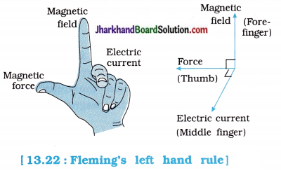
(ii) Fleming’s left-hand rule : In this case, Fleming’s left hand rule is used to find the direction of the force acting on the conductor.
Fleming left-hand rule:
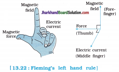
Stretch the thumb, forefinger and middle finger of your left hand such that they are mutually perpendicular (figure 13.22). If the first (fore) finger points in the direction of magnetic field and second (middle) finger points in the direction of current, then the thumb will point in the direction of motion or the force acting on the conductor.
Note : Experimentally it is found that, when direction of current through the rod and direction of the magnetic field are perpendicular to each other, the force exerted on the rod is perpendicular to both of them.
(iii) Fleming’s right-hand rule : Direction of induced current in a conductor can be known with the help of Fleming’s right-hand rule.
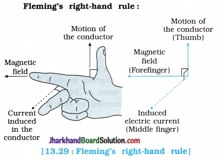
Stretch the thumb, forefinger and middle finger of right hand so that they are perpendicular to each other. If forefinger indicates the direction of the magnetic field and thumb shows the direction of motion of conductor, then the middle finger will show the direction of induced current.
Question 16.
Explain the underlying principle and working of an electric generator by drawing a labelled diagram. What is the function of the brushes?
Answer:
Principle : When a coil is rotated properly in a magnetic field, electromotive force is induced in it. As a result, a current flows in the circuit containing the coil.
OR
When a coil is rotated in a magnetic field, electric current is induced in the circuit containing the coil.
Labelled diagram and working : An electric generator is a device that converts mechanical energy into electrical energy. Its working is based on electromagnetic induction.
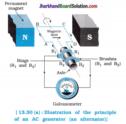
Construction :
- Figure 13.30 (a) shows the construction of an AC generator. It consists of a rectangular coil ABCD placed between the two poles of a permanent magnet.
- Two ends of this coil are connected to the two metal (copper) rings R1 and R2. The inner side of these rings are insulated.
- The two conducting stationary brushes R1 and R2 are kept pressed separately on the rings R1 and R2 respectively.
- The two rings R1 and R2 are internally attached to an axle. The axle may be mechanically rotated from outside to rotate the coil inside the magnetic field.
- Outer ends of the two brushes are s connected to the galvanometer to show the flow of current in the given external circuit.
Working:
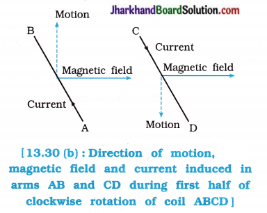
(1) Suppose, the axle attached to the two rings is rotated such that the arm AB moves up and the arm CD moves down in the magnetic field produced by the permanent magnet. Then the coil ABCD rotates clockwise in the arrangement shown in the figure. By applying Fleming’s right- hand rule, we find that the induced currents are set up in these arms along the directions AB and CD. This means that the current in external circuit flows from brush B2 to B1.
[If the coil is made of a larger number of turns, the current generated in each turn adds up to give a large current through the coil.]
(2) After half a rotation, arm CD starts moving up and AB moving down. As a result, the directions of the induced currents in both the arms change, giving rise to the net induced current in the direction DCBA. This means that the current in the external circuit now flows from brush B1 to B2.
(3) Thus, after every half rotation the direction of the current in the respective arms changes. Such a current, which changes direction after equal intervals of time, is called an alternating current (abbreviated as AC).
The function of the brushes in an electric generator : Brushes are used to transmit current induced externally from coil ABCD to the external circuit.
![]()
Question 17.
When does an electric short circuit occur?
Answer:
An electric short circuit takes place when the live wire and neutral wire of the electric supply line touch each other directly or indirectly via a conducting wire. This occurs when the plastic insulation of the wires gets torn or there is a fault in the electrical appliance.
Question 18.
What is the function of an earth wire? Why is it necessary to earth metallic appliances?
Answer:
Function of an earth wire : The function of an earth wire is to provide a low-resistance conducting path to the current leaking from an electrical appliance to the earth and thereby prevent electric shock to the user of the electrical appliance.
Therefore, it is necessary to earth metallic appliances such as an electric press, toaster, table fan, refrigerator, etc.
Sometimes accidently, the insulation of the wires connected to an electrical appliances may melt resulting in a current through the metallic casing of the appliance. A person touching such an appliance may get a severe electric shock which can be fatal. To avoid this, the current should be diverted to the earth.
Moreover, due to very low resistance (almost nil) offered by the earth wire, the current in the circuit rises to a very high value, thereby melting fuse in that circuit and cutting off its electric supply.
Thus, earthing the electrical appliances properly, saves us from possible electric shock.
Jharkhand Board Class 10 Science Magnetic Effects of Electric Current InText Questions and Answers
Question 1.
Why does a compass needle get deflected when brought near a bar magnet?
Answer:
A compass needle is a small bar magnet with one north pole and the other south pole. When a compass is brought near a bar magnet, compass needle gets deflected due to the forces acting on its pole due to the magnetic field of the bar magnet.
Note: When compass needle is brought near a bar magnet it is acted upon by the force due to the magnetic field of the earth as well as that due to the bar magnet. Therefore, it gets deflected and finally comes to rest in the direction of the net force.
Question 2.
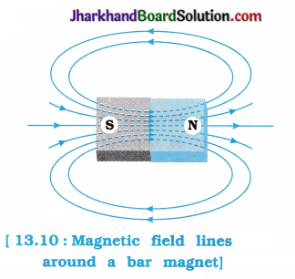
Draw magnetic field lines around a bar magnet.
Answer:
Question 3.
List the properties of magnetic field lines.
Answer:
(1) The magnetic field lines emerge from north pole and merge at the south pole outside the magnet, while inside the magnet the direction of field lines is from its south pole to its north pole.
Thus, the magnetic field lines are closed and continuous curve.
(2) The magnetic field lines are crowded near the pole where the magnetic field is strong and are far apart near the middle of the magnet and far from the magnet where the magnetic field is weak.
(3) The magnetic field lines never intersect each other because if they do so, there would be two directions of magnetic field at that point which is absurd.
(4) In case the field lines are parallel and equidistant, these represent a uniform magnetic field.
Important note : The relative strength of the magnetic field is shown by the degree of closeness of the field lines.
Question 4.
Why don’t two magnetic field lines intersect each other?
Answer:
The direction of the magnetic field B at a point is obtained by drawing a tangent to the magnetic field line at that point.
If two magnetic field lines intersect each other, it would mean that there are two directions of the magnetic field at the point of intersection, which is not possible because magnetic field is a vector, at a given point in space, it can have only one direction, (or the resultant force on a pole (north / south) at any point can only be in one direction.)
Question 5.
Consider a circular loop of wire lying in the plane of the table. Let the current pass through the loop clockwise. Apply the Right-hand thumb rule to And out the direction of the magnetic field inside and outside the loop.
Answer:
Using the Right-hand thumb rule, the direction of the magnetic field inside and outside the circular loop of wire carrying an electric current can be found. This is shown in the following figure:
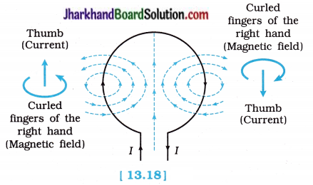
The dotted magnetic field lines are perpendicular to the plane of the paper.
The front face of the loop behaves as the south pole and the back face, i.e., the face touching the plane of the table behaves as the north pole.
Question 6.
The magnetic field in a given region is uniform. Draw a diagram to represent it.
Answer:
A uniform magnetic field in a given region can be represented by straight, parallel equally spaced field lines.

Question 7.
Choose the correct option :
The magnetic field inside a long straight solenoid carrying current…
(a) is zero.
(b) decreases as we move towards its end.
(c) increases as we move towards its end.
(d) is the same at all points.
Answer:
(d) is the same at all points.
Hint: The magnetic field inside a long straight current-carrying solenoid is uniform which is represented by straight parallel equally spaced lines. Thus, it is the same at all the points.
Question 8.
Which of the following property of a proton can change while it moves freely in a magnetic field? (There may be more than one correct answer.)
(a) mass
(b) speed
(c) velocity
(d) momentum
Answer:
(c) velocity and
(d) momentum
Hint: The proton is a charged particle. Whenever a charged particle moves in a magnetic field except in the direction of the magnetic field and opposite to the direction of the magnetic field, a magnetic force exerts on it. As a result its velocity and momentum (mass x velocity) both change.
Note: The magnetic force is perpendicular to the velocity of the charged particle (here, the proton). Therefore, only the direction of the velocity of the particle changes, i.e., there is no change in magnitude of the velocity (speed) of the particle. The mass does not change.
![]()
Question 9.
In Activity 13.7. how do we think the displacement of the rod AB will be affected if (i) the current in rod AB is increased; (ii) a stronger horse-shoe magnet is used; and (iii) the length of the rod AB is increased?
Answer:
Experiments have shown that, when a current-carrying conductor is placed in a magnetic field such that its length is perpendicular to the magnetic field, the force acting on the conductor and hence its displacement (as the conductor is initially at rest) is proportional to…
- the current in the conductor
- the strength of the magnetic field
- the length of the conductor
(i) When the current in the rod AB is increased, then more force will act on the rod and hence the displacement of the rod will also be more (in the same proportion).
(ii) If a stronger horse-shoe magnet is used, then the strength of magnetic field will increase leading to a greater force on the rod. Due to the greater force, the displacement of the rod will also be more (in the same proportion.).
(iii) If the length of the rod AB is increased, then more force will act on the rod and hence the displacement of the rod will also be more (in the same proportion).
Question 10.
A positively charged particle (alpha particle) projected towards west is deflected towards north by a magnetic field. The direction of magnetic field is…
(a) towards south
(b) towards east
(c) downward
(d) upward
Answer:
(d) upward
Hint:
- Here, the positively charged particle (alpha particle) is initially moving towards the west, so the direction of the corresponding conventional current (current opposite to electron-current) is towards the west.
- The deflection of alpha particle is towards north. This shows that the magnetic force acts on it towards the north (direction).
- Hence, here (a) direction of current I is towards west and (b) direction of force F is towards north
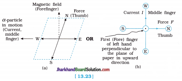
- Let us now hold the first (fore) finger, middle finger and thumb of your left hand at right angles to one another.
- Adjust the left hand in such a way that your middle finger points towards the west (in the direction of the current) and the thumb points towards the north (in the direction of the force.)
In this case, your first (fore) finger points upwards [shown by the symbol G], Since the direction of the forefinger gives the direction of the magnetic field, the magnetic field would be in the upward direction, [see figure 13.23 (a) or 13.23 (b)].
Question 11.
State Fleming’s left-hand rule.
Answer:
In this case, Fleming’s left hand rule is used to find the direction of the force acting on the conductor.
Fleming left-hand rule:
Stretch the thumb, forefinger and middle finger of your left hand such that they are mutually perpendicular (figure 13.22). If the first (fore) finger points in the direction of magnetic field and second (middle) finger points in the direction of current, then the thumb will point in the direction of motion or the force acting on the conductor.
Note : Experimentally it is found that, when direction of current through the rod and direction of the magnetic field are perpendicular to each other, the force exerted on the rod is perpendicular to both of them.
Question 12.
What is the principle of an electric motor?
Answer:
When a rectangular coil carrying a current is placed in a magnetic field, then forces, equal in magnitude and opposite in direction, act on its two parallel sides, perpendicular to their lengths, due to which the coil rotates continuously.
Question 13.
What is the role of the split rings s in an electric motor?
Answer:
The split rings act as a commutator and its function is to reverse the direction of the current flowing through the coil after every half rotation of the coil.
Due to reversing of the current, the direction of rotating couple (i.e., torque) remains unchanged and the coil continues to rotate in the same direction.
Question 14.
Explain different ways to induce a current in a coil.
Answer:
- A current can be induced in a coil by moving a magnet towards or away from it or by moving the coil towards or away from the magnet.
- A current can be induced in a coil by changing the current in the coil placed near it.
- A current can be induced in a coil by moving a coil properly in a non-uniform magnetic field or by changing a magnetic field around steady coil by some means.
- A current can be induced in a coil by rotating it properly in a magnetic field or by rotating a magnet properly placed near the coil.
[Note : The magnet used may be a bar magnet or a current-carrying conductor.]
Question 15.
State the principle of an electric generator.
Answer:
The working of an electric generator is based upon the principle of electromagnetic induction.
Principle : An electric current produced in a closed circuit or coil by a changing magnetic field is called an induced current. This phenomenon is called electromagnetic induction.
Question 16.
Name some sources of direct current.
Answer:
Electrochemical dry cells, batteries, DC generators, solar cells, etc. are sources of direct current (DC).
Question 17.
Which sources produce alternating current?
Answer:
AC generators (or powerhouse generators), car alternators, bicycle dynamos are sources of alternating current (AC).
Question 18.
Choose the correct option :
A rectangular coil of copper wires is rotated in a magnetic field. The direction of the induced current changes once in each…
(a) two rotations
(b) one rotation
(c) half rotation
(d) one-fourth rotation
Answer:
(c) half rotation
Hint: After each half rotation, the direction of motion of the two parallel sides of the coil (AB and CD) is reversed and so the direction of the induced current changes once in each half rotation.
Question 19.
Name two safety measures commonly used in electric circuits and appliances.
Answer:
- A safety fuse of proper rating : It prevents damage to the appliances and circuit due to overloading.
- An earth wire : It prevents possible electric shock when the live wire accidentally touches the metallic body of an appliance.
Question 20.
An electric oven of 2 kW power rating is operated in a domestic electric circuit (220 V) that has a current rating of 5 A. What result do you expect? Explain.
Answer:
The current drawn by this electric oven,
I = \(\frac { P }{ V }\)
= \(\frac { 2000 W }{ 220 V }\)
= 9.09 A
Since the current rating of the circuit is 5 A. the fuse used in this circuit is only of 5 A capacity.
Hence, when the oven is switch ON, the fuse wire (rated 5 A) will get heated too much, melt and break the circuit. This will save the electric oven from getting damaged.
[If fuse of current rating more than 9.09 A is used in the circuit or if no fuse has been put in the circuit, there may be a fire.]
Question 21.
What precaution should be taken to avoid the overloading of domestic electric circuits?
Answer:
To avoid overloading of domestic electric circuits, the following precautions should be taken :
- Wires used for carrying current should be of proper current rating.
- Two separate circuits should be used, one of 5 A current for lighting electric bulbs, tubes, TV, etc. and another of 15 A for higher current rating appliances such as heating appliances, AC, etc.
- Parallel circuits should be used and each circuit should have a fuse of proper rating.
- Too many higher power rating electrical appliances such as electric iron, geyser, air-conditioner, etc. should not be switched on at the same time.
- Too many electrical appliances should not be operated on a single socket simultaneously.
- Wires should be replaced by new wires of proper rating and good insulation after every 5-6 years.
- PVC of good quality should be used.
Activity 13.1 [T. B. Pg. 223]
To show that the magnetic field is produced s due to electric current.
Procedure:
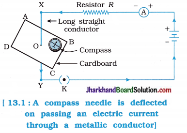
1. Take a straight thick copper wire and place it between points X and Y in an electric circuit, as shown in figure 13.1. Wire XY is kept perpendicular to the plane of the paper.
2. Horizontally place a small compass near this copper wire.
See the position of its needle.
3. Pass the current through the circuit by inserting the key into the plug.
- Observe the change in the position of the compass needle.
- What does it indicate? (or What does it mean?)
Observation:
1. When no current flows in the straight thick copper wire (i.e., when plug key K is open), the compass needle (i.e., magnetic needle) remains stationary in the geographical north- south direction of the earth.
2. On passing the current through the copper wire XY (i.e., conducting wire), by inserting the key into the plug, compass needle is deflected.
[Any change in the direction of current through copper wire will show a variation in deflection.]
3. This indicates (shows) that the electric current through copper wire (the conductor) has produced a magnetic effect. It means that magnetic field is produced around the (copper) wire.
Conclusion :
Magnetic field is produced due to electric current. Thus, we can say that +electricity and ++magnetism are linked to each other.
Note: The ‘magnetic effect of electric current’ means that an electric current flowing in a conducting wire produces a magnetic field around it.
Activity 13.2 [T. B. Pg. 224]
To understand the magnetic field produced by a bar magnet.
OR
To obtain the magnetic field lines around a bar magnet.
Procedure :
1. Fix a sheet of white paper on a drawing board using some adhesive material.
2. Place a bar magnet in the centre of it.
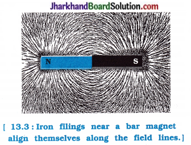
3. Sprinkle some iron filings uniformly around a bar magnet as shown in figure 13.3. A salt- sprinkler may be used for this purpose.
4. Now tap the board gently.
- What do you observe?
- Why do the iron filings arrange in such a pattern?
- What does this pattern demonstrate?
Observation :
1. The iron filings arrange themselves in a pattern as shown in figure 13.3.
2. A bar magnet exerts its influence in the region surrounding it. Therefore, the iron filings experience a magnetic force. This force makes iron filings arrange in a specific (particular) pattern.
3. The region surrounding a magnet, in which the force of the magnet can be detected, is said to have a magnetic field.
The lines along which the iron filings align themselves represent magnetic field lines.
Conclusion:
A bar manget possesses a magnetic field which can be detected by sprinkling iron filings around it.
![]()
Activity 13.3 [T. B. Pg. 224]
To draw magnetic field lines of a bar magnet using a compass.
Procedure:
1. Take a small compass and a bar magnet.
2. Place the magnet on a sheet of white paper fixed on a drawing board, using some adhesive material.
3. Mark the boundary of the magnet.
4. Place a compass near the north pole of the magnet. How does it behave?
5. Mark the positions of two ends of the needle.
6. Now move the needle to a new position such that its south pole occupies the position previously occupied by its north pole.
In this way, proceed step by step till you reach the south pole of the magnet as shown in figure 13.4.
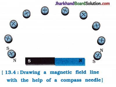
7. Join the points marked on the paper by a smooth curve. This curve represents a magnetic field line.
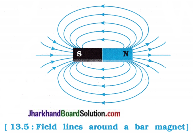
8. Repeat the above procedure and draw as many lines as you can. You will get a pattern shown in figure 13.5.
These lines represent the magnetic field around the magnet.
These are known as magnetic field lines.
- Observe the deflection in the compass needle as you move it along a field line. The deflection increases as the needle is moved towards the poles.
Observation:
1. The south pole of the needle points towards the north pole of the magnet. The north pole s of the compass needle is directed away from the north pole of the magnet.
2. Magnetic field is a quantity that has both direction and magnitude. The direction of the magnetic field is taken to be direction in which a north pole of the compass needle moves inside it.
Therefore, the field lines emerge from the north pole and merge at the south pole of a magnet. Inside the magnet, the direction of the field lines is from its south pole to its north pole. Thus, the magnetic field lines are closed curves.
Conclusion:
- The region surrounding a magnet has a magnetic field, i.e., a bar magnet possesses magnetic field.
- The direction of magnetic field is the direction in which the north pole of the compass needle move / deflect.
- The field is stronger where the field lines are crowded and weaker where the field lines are farther away from each other.
- The deflection of the needle increases as the needle is moved towards the poles.
Activity 13.4 [T. B. Pg. 226]
To show that the direction of the magnetic field due to a current depends on the direction of the current.
Procedure:
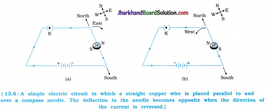
1. Take a long straight copper wire, two or three cells of 1.5 V each, and a plug key. Connect all of them in series as shown in figure 13.6 (a).
2. Place the straight wire parallel to and over a compass needle.
3. Plug the key in the circuit.
Observe the direction of deflection of the north pole of the needle.
4. Replace the cell connections in the circuit as shown in figure 13.6 (b). This would result in the change of the direction of current through the copper wire, that is, from south to north.
Observe the change in the direction of deflection of the needle.
Observation:
1. If the current flows from north to south as shown in figure 13.6 (a), the north pole of the compass needle moves towards the east.
2. Now, when the current flowing through the copper wire is reversed, the compass needle aligns / moves in the opposite direction i.e., towards the west as shown in figure 13.6 (b).
It means that the direction of the magnetic field due to a current is reversed, when the direction of the current is reversed.
Conclusion :
The direction of the magnetic field due to a current depends on the direction of the current.
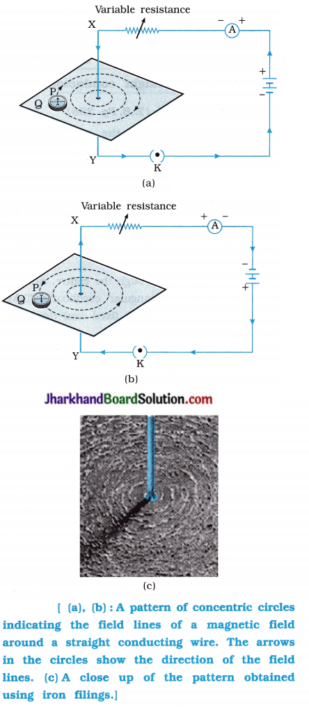
Activity 13.5 [T. B. Pg. 226]
To study the pattern of the magnetic field (lines) due to a current through a straight conductor.
Procedure:
1. Take a battery (12 V), a variable resistance (or a rheostat), an ammeter (0-5 A), a plug key, connecting wires and a long straight thick copper wire.
2. Insert the thick wire through the centre, normal to the plane of a rectangular cardboard. Take care that the cardboard is fixed and does not slide up or down.
3. Connect the copper wire vertically between the points X and Y, as shown in figure 13.7 (a), in series with the battery and a plug key.
4. Sprinkle some iron filings uniformly on the cardboard. (You may use a salt-sprinkler for this purpose.)
5. Close the key so that a current flows through the wire. Ensure that the copper wire placed between the points X and Y remains vertically straight.
6. Keep the variable of the variable resistance (or rheostat) at a fixed position and note the current through the ammeter.
- Gently tap the cardboard a few times. Observe the pattern of the iron filings.
- What do these concentric circles represent?
- How can the direction of the magnetic field be found?
(Place a compass at a point (say P) over a circle. Observe the direction of the needle.) - Does the direction of the magnetic field lines get reversed if the direction of the current through the straight copper wire is reversed? Check it.
- What happens to the deflection of the compass needle placed at a given point if the current in the copper wire is changed?
- (To see this, vary the current in the wire using the variable resistance.)
- What happens to the deflection of the needle if the compass is moved away from the copper wire keeping the current through the wire remains tire same?
- (To see this, now place the compass needle at a farther point from the conducting wire [say at point Q (figure 13.7 (b)]).
- What change do you observe?
Observation:
- It is found that the iron filings align themselves forming a pattern of concentric circles around the copper wire (figure 13.7 (c)).
- These concentric circles represent the (pattern of) magnetic field lines.
- The direction shown by the north pole of the compass needle gives the direction of the magnetic field lines at point P. In figure 13.7 (a), it is shown by an arrow.
- Yes. The direction of the magnetic field lines get reversed if the direction of the current through the straight copper wire is reversed (see figure 13.7 (b)).
- We find that the deflection of the needle changes, when the current is changed.
If the current is increased, the deflection increases and if the current is decreased, the deflection decreases.
- When the compass is moved away from the wire, the deflection of the needle decreases.
- When the compass is moved away from the wire, it is observed that the concentric circles representing the magnetic field around a current-carrying straight wire become larger and larger.
- In other words, as we move away from the wire, the radius of a circle representing the magnetic field line increases.
Conclusion :
(1) Pattern of the magnetic field produced due to a straight conductor carrying current is concentric circles, which are nothing but the magnetic field lines of the produced magnetic field.
(2) Direction of magnetic field at a point is in the direction of tangent drawn at that point on particular circle, which is nothing but the direction of north pole of compass needle at that point.
(3) Direction of magnetic field lines get reversed if direction of current through the straight copper wire is reversed, i.e., it depends on the direction of the current.
(4) Magnitude of the magnetic field produced at a given point increases as the current through the wire increases.
i.e., Magnetic field B ∝ Current I.
(5) Magnitude of the magnetic field produced by a given current in the conductor decreases as the distance from wire increases.
i.e., Magnetic field B ∝ \(\frac{1}{\text { Distance from the wire }}\)
Activity 13.6 [T. B. Pg. 229]
To study the magnetic field produced near a circular coil carrying current.
Procedure:
- Take a rectangular cardboard having two holes. Insert a circular coil having a large number of turns through them, normal to the plane of the cardboard.
- Connect the ends of the coil in series with a battery, a plug key and a rheostat, as shown in figure 13.13.
- Sprinkle iron filings uniformly on the cardboard.
- Plug the key.
- Tap the cardboard gently a few times.
- Note the pattern of the iron filings that emerges on the cardboard.
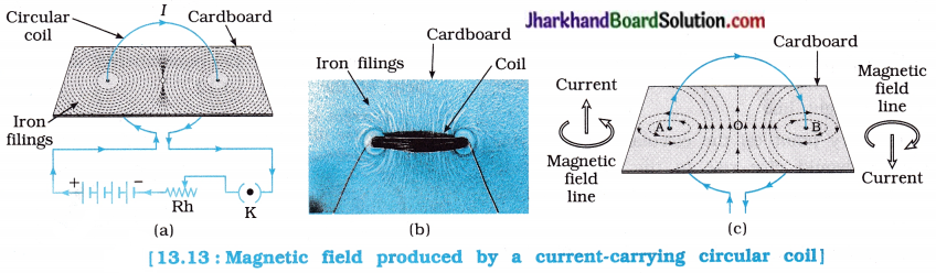
Observation :
The iron filings arrange themselves in the pattern as shown in figure 13.13.
Conclusion:
- The magnetic field at the centre of the coil is nearly uniform.
- The magnetic field lines near the coil are circular and concentric.
- At the centre, as the field lines are crowded, the strength of the magnetic field is maximum.
![]()
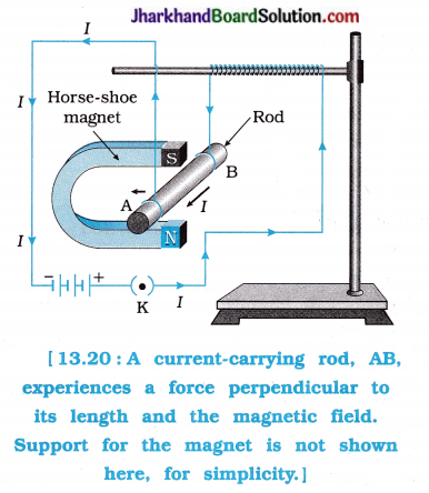
Activity 13.7 [T. B. Pg. 230]
To understand the force experienced by a current-carrying small aluminium (conducting) rod placed in a magnetic field.
Procedure:
1. Take a small aluminium rod AB (of length about 5 cm.) Using two connecting wires suspend it horizontally from a stand, as shown in figure 13.20.
2. Place a strong horse-shoe magnet in such a way that the rod lies between the two poles with the magnetic field directed upwards. For this put the north pole of the magnet vertically below and the south pole vertically above the aluminium rod (see figure 13.20).
3. Connect the aluminium rod in series with a battery, a plug key and a rheostat.
4. Now pass a current through the aluminium rod from end B to end A.
- What do you observe?
- Reverse the direction of current flowing through the rod and observe the direction of its displacement.
- Why does the rod get displaced?
- Change the direction of magnetic field by interchanging the two poles of the magnet to vertically downwards and observe the direction of the force / displacement of the current-? carrying rod.
Observation :
1. It is observed that the rod is displaced to the left.
2. The direction of the displacement of the rod is reversed, i.e., now it is to the right, on reversing the direction of the current flowing through the rod.
It suggests that the direction of the force is also reversed when the direction of the current through the conductor (rod) is reversed.
3. The displacement of the rod is due to the force exerted on the current- carrying aluminium rod when it is placed in a magnetic field.
4. The direction of the force acting on the current-carrying rod and hence that of the displacement of the rod (as the rod is initially ; at rest) gets reversed on changing the direction of the magnetic field to vertically downwards.
Conclusion :
- A current-carrying conductor (here a rod) experiences a force when placed in a magnetic field.
- The direction of the force and hence that of the displacement of the conductor (rod) depends upon the direction of the current and the direction of the magnetic field.
Notes :
- Here, the displacement of the rod has the same direction as that of the force acting on the rod because the rod is initially at rest. Recall the kinematical equations.
- The magnetic force also depends upon the length of the rod in the magnetic field.
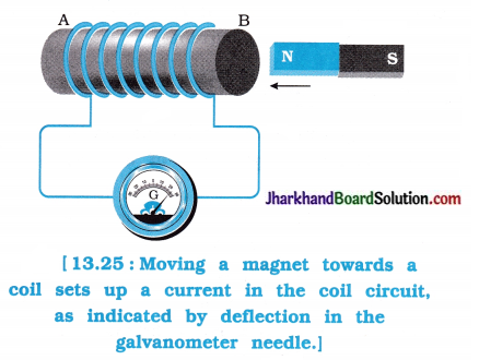
Activity 13.8 [T. B. Pg. 233]
To study the phenomenon of electromagnetic induction.
Procedure:
1. Take a coil of wire AB having a large number of turns.
2. Connect the ends of the coil to a galvanometer as shown in figure 13.25.
3. Take a strong bar magnet and move its north pole towards the end B of the coil.
Do you find any change in the galvanometer needle?
4. Now withdraw the north pole of the magnet away from the coil.
What do you observe?
5. Place the magnet stationary at a point near the coil, keeping its north pole towards the end B of the coil.
6. Move the coil to right and later to left.
What do you observe?
7. When the coil is kept stationary with respect to the magnet.
What do you observe?
8. Now, move the south pole of the magnet towards the end B of the coil.
- What do you observe?
- When the coil and the magnet both are stationary what do you observe?
- What do you conclude from this activity?
Observation :
1. There Is a momentary deflection in the needle of the galvanometer, say to the right.
This indicates the presence of a current in the coil AB. The deflection becomes zero the moment the motion of the magnet stops.
2. When the north pole of the magnet is moved away from the coil, the galvanometer needle is deflected to the left, showing that the current is now set up in the direction opposite to the first.
3. We see that the galvanometer needle deflects to the right when the coil is moved towards the north pole of the magnet. Similarly, the needle moves to the left when the coil is moved away.
4. When the coil is kept stationary with respect to the magnet, the deflection of the galvanometer needle drops to zero.
5. If you move the south pole of the magnet ‘c towards the end B of the coil, the deflections in the galvanometer would just be opposite > to those in the previous case.
6. When the coil and magnet both are stationary, there is no deflection in the galvanometer.
Conclusion :
Whenever there is a relative motion between s a magnet and coil, potential difference is produced between two ends of the coil, which sets up an electric current in the circuit.
This potential difference is called the induced potential difference and the corresponding current is called the induced current.
Activity 13.9 [T. B. Pg. 235]
To study the phenomenon of electromagnetic induction.
Procedure:
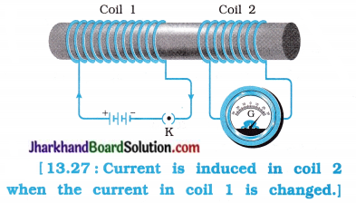
1. Take two different coils of copper wire having large number of turns (say 50 and loo turns respectively). Insert them over a non-conducting cylindrical roll, as shown in figure 13.27 (You may use a thick paper roll for this purpose.)
2. Connect the coil 1. having larger number of turns, in series with a battery and a plug key. Also connect the other coil 2 wIth a galvanometer as shown.
3. Plug in the key. Observe the galvanometer.
Is there a deflection in its needle?
4. Disconnect coil 1 from the battery.
What do you observe?
Observation :
1. When the key is plugged, the needle of the galvanometer is instantly deflected to one side and then quickly returns to zero, indicating a momentary current in coil 2.
2. When coil 1 is disconnected from the battery, the needle of the galvanometer momentarily moves, but to the opposite side, i.e., now the current flows in the opposite direction in coil 2.
In short in this activity, we observe that as soon as the current in coil 1 reaches either a steady value or becomes zero, the galvanometer connected to coil 2 shows no deflection.
Conclusion :
(a) A potential difference is induced in coil 2 whenever the electric current through the coil 1 changes with time.
(b) As the current in coil 1 (which is called Primary coil) changes, the magnetic field associated with it also changes. Then the magnetic field lines around coil 2 (which s is called Secondary coil) also change.
Thus, the change in magnetic field lines associated with the secondary coil is the cause of induced electric current in it. s
This process, by which a changing magnetic field in a conductor induces a current in another conductor, is called electromagnetic induction.